Round Wedged Prisms


Please Wait
Application Ideas
- Introduction and Setup
- Tracing a Circle with One Prism
- Tracing a Circle with Two Prisms
- Tracing a Spiral with Two Prisms
Click to Enlarge
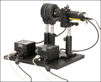
Figure 1.1 Risley Prism Scanner Using Previous-Generation TDC001
Introduction and Setup
Wedge prisms are designed to be used, either individually or in a pair, for beam steering applications. This is done by individually controlling the rotation of each prism using our PRM1Z8 motorized rotation stages. Tables 1.2 and 1.3 correspond to either the imperial or metric product list for the configuration pictured in Figure 1.1. Clicking on the item number will bring up a pop-up window with more information about that component.
An Application Note was prepared to describe this process in further detail, and will be referenced periodically here. For a full download of the Application Note, click here. An Excel Spreadsheet that can be used to model a Risley Prism Scanner can be downloaded here.
Note: Figure 1.1 shows a previous generation TDC001 T-Cube and previous-generation KPS101 Power Supplies.
Click to Enlarge
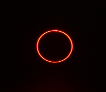
Figure 1.4 Long-Exposure Photograph of a Circle
Traced with One Prism
Tracing a Circle with One Prism
For this application, only one prism was mounted in a rotation mount. The incoming beam was deviated off axis by the wedge prism. Once the rotation mount was activated, the wedge prism was spun about the optical axis, which caused the deviated beam to trace out a small circle, as shown in the long-exposure photograph in Figure 1.4. The radius of this circle can be calculated as:

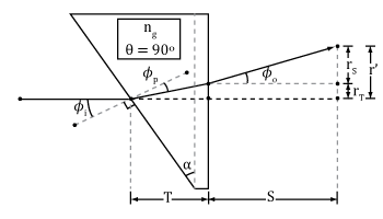
This is equation 9 in the Application Note linked above. In this equation r' is this circle's radius, S is the distance from the last surface of the prism to the scanning surface, T is the center thickness of the prism, Φo is the beam angle relative to the original optical axis after exiting the second surface of the prism, Φi is the angle created from the beam's incidence on the first surface of the prism according to Snell's Law, and Φp is the resulting angle the beam takes inside the prism relative to the first surface's normal according to Snell's Law.
Click to Enlarge
Figure 1.5 The beam path of a monochromatic source incident on the wedged side of a round wedged prism, which has its thickest section defined as vertical. Diagram is not to scale.
Click to Enlarge
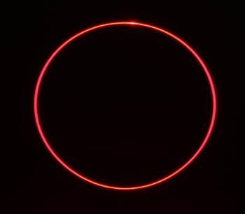
Figure 1.6 Long-Exposure Photograph of a Circle
Traced with Two Prisms
Tracing a Circle with Two Prisms
For this application, the rotation mounts are set so that the wedges of both prisms are aligned to the home position, where both prisms' thickest sections are vertical. Since each prism will deviate the beam by the deviation angle, the total beam deviation for two prisms with the wedges aligned will be approximately twice the size. If both prisms are rotated at the same rate and in the same direction, the beam will trace out a circle which is approximately twice the size of the circle traced out by a single prism. The long-exposure photograph in Figure 1.6 was taken with the prism assembly at the same distance from the screen as the one-prism circle above. Notice that the circle in the two-prism case is about twice the diameter of the one formed with one prism. The radius of this circle can be calculated as:

This is equation 18 in the Application Note linked above. In this parametric equation, rmax is the radius of this circle (any subsequent shape created by this setup is enclosed by this radius), T is the middle thickness of the fist prism, T' is the effective thickness of prism 2 after the deviated beam travels through it, Φi is the angle created from the beam's incidence on the first surface of the fist prism according to Snell's Law, Φp is the resulting angle the beam takes inside the prism relative to the first surface's normal according to Snell's Law, z is the distance from the second surface of the second prism to the scanning surface, S is the distance between the prisms, and Φo is the beam angle relative to the original optical axis after exiting the second surface of the first prism.
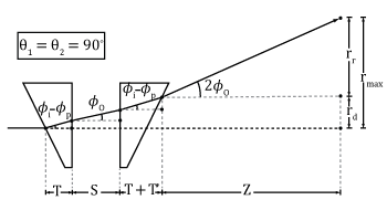
Click to Enlarge
Figure 1.7 The beam path taken through a Risley Prism Scanner when both prisms are in the home position, giving the maximum displacement of the beam. Diagram is not to scale.
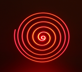
Click to Enlarge
Figure 1.8 Long-Exposure Photograph of a Spiral
Traced with Two Prisms
Tracing a Spiral with Two Prisms
It can be shown that a large variety of shapes can be traced while rotating the two prisms at constant speeds. These shapes are dictated by the equation:

This is equation 21 in the Application Note linked above; please reference that Application Note or the accompanying spreadsheet for the definitions of these variables. As an example, the long-exposure photograph in Figure 1.8 shows two wedge prisms being used to trace out a spiral. This was realized by first setting the beam to be undeviated, and then having the prisms rotate in the same direction, with one prism set to rotate 0.5 deg/s faster than the other. This, and many other shapes, can be created on the "Third Approx." sheet of the downloadable Excel sheet above. To create this spiral, try inputting 25 deg/s to ω1 (rotation speed of prism 1), 24.5 deg/s to ω2 (rotation speed of prism 2), and 80 seconds to t (run time), with a Δθ (home position offset) of 180 degrees.
| Posted Comments: | |
| No Comments Posted |
 Products Home



 Round Wedge Prism