 Products Home / Lab Supplies / Temperature Control and Measurement / Heater and TEC Temperature Controller
Heater and TEC Temperature Controller
- Heating Set Point from -200 °C to 400 °C
- Two Channels Capable of Independent or Synchronized Operation
- User-Configurable PID with Auto-Tuning Function
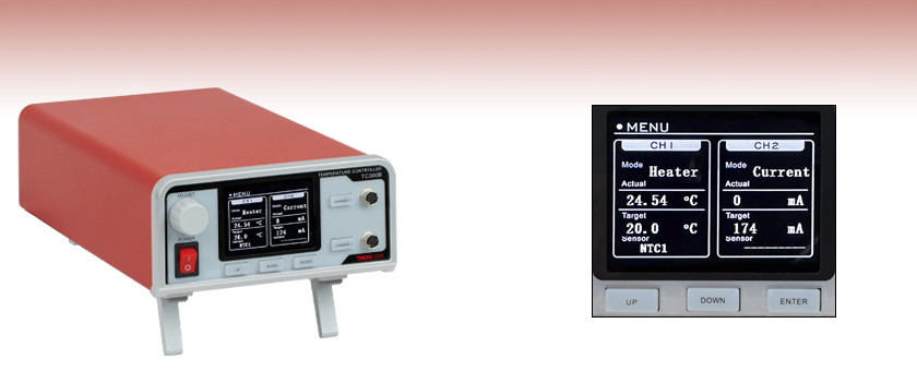
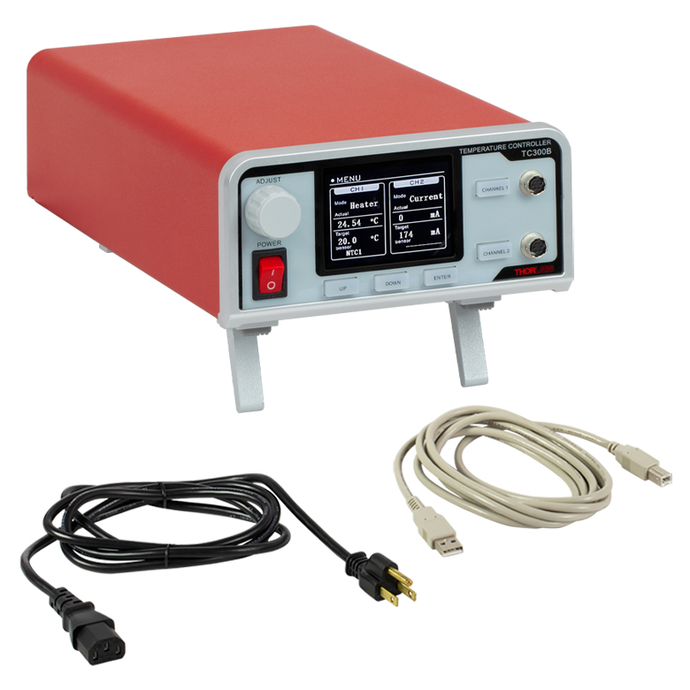
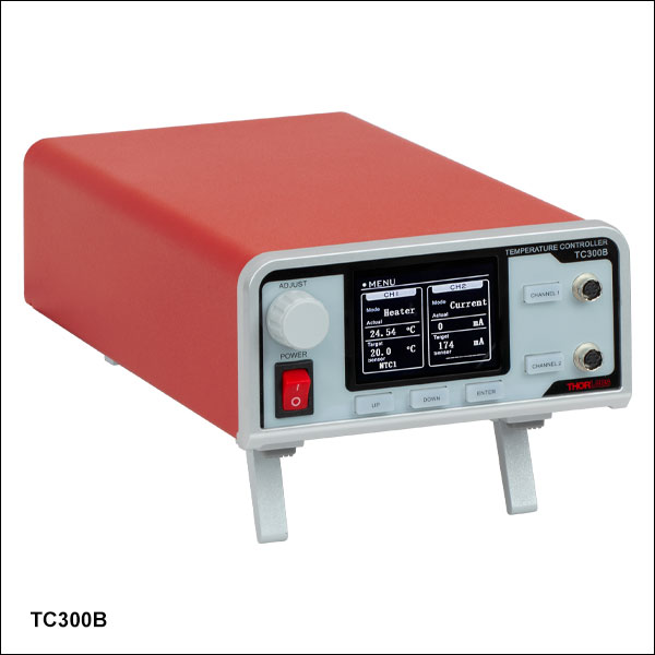
TC300B
Heater and TEC Temperature Controller
Front Panel Allows Stand-Alone Operation


Please Wait
| Specifications | |
|---|---|
| Output Power per Channel | 48 W (Max) |
| Output Current per Channel | 2 A (Max) |
| Output Voltage per Channel | 24 V (Max) |
| Temperature Setting Range | -200 to 400 °Ca |
| Set Point Resolution | 0.1 °C / 0.001 °Cb |
| Temperature Stability | ±0.1 °C |
| Sensor Types | Thermistorc, AD590, Thermocoupled, 2-Wire and 4-Wire Platinum 100 Ω, 2-Wire and 4-Wire Platinum 1000 Ω |
| Output Connector Type | Hirose HR10A-7R-6S(73) |
| USB Interface | USB 2.0 Type-B |
| Power Supply | 100 - 240 VAC, 50 - 60 Hz, 165 VA Max |
| Operating Temperature | 0 - 40 °C |
| Storage Temperature | -15 - 65 °C |
| Dimensions (H x W x D) | 86.6 mm x 154.3 mm x 327.8 mm (3.41" x 6.07" x 12.91") |
| Weight | 1.7 kg |
Features
- Dual-Channel Resistive Heater Controller
- Can Drive Resistive Heating Elements and Thermoelectric Cooler (TEC) Devices
- Three Control Modes
- User-Configurable, Closed-Loop PID Control with Auto-Tuning Function
- Constant-Current, Open-Loop Operation
- Cycle Mode for Executing User-Defined, Closed-Loop Ramp and Hold Procedures
- High-Resolution Temperature Measurement and Control Available When Using NTC Thermistors
- Run Standalone, via PC Software, or via C/C++ and Labview SDKs
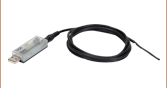
- Compatible 6-Pin Hirose Cables Available:
- 3.0 m (9.84') HR10CAB1 Male-to-Male Cable
- 1.8 m (5.90') HR10AD1 Cable with Breakout Box for Custom Applications
Thorlabs' TC300B Heater and TEC Temperature Controller is a general-purpose benchtop controller intended for use with resistive heating elements, including foil (such as Item # HT10K) and resistive coil (such as Item # HT15W) types. It also accepts feedback from a variety of temperature sensor types including positive (such as Item # TH100PT) or negative (such as Item # TH10K) temperature coefficient thermistors and thermocouples with a resolution of 0.1 °C. When configured with negative temperature coefficient (NTC) thermistors, a high-resolution mode offers temperature resolution of 0.001 °C.
The two channels of the TC300B controller are capable of either independent or synchronized operation. Each channel has PID control with programmable P, I, and D gains as well as an auto-tune function. The back of the TC300B controller has connectors for analog inputs and outputs as well as output triggers for each channel. An output proportional to the actual temperature of the channel is given in the analog output, and the input and output trigger allows the user to enable or disable the channel. For more information, please see the Front & Back Panel tab.
User-programmable maximum temperature and current/voltage limits protect the connected heating element from being overheated or over driven. Other safety features include an Open Sensor Alarm that will shut down the driver if the temperature sensing element is missing or becomes disconnected.
A simple keypad interface allows stand-alone operation, but the TC300B controller can also be connected to a PC using the included USB Type-B cable and our TC300B Software. Interfacing with a PC can also be achieved by using LabVIEW® or LabWindows with a simple command-line interface from any terminal window. Please see the Software tab for more information.
The TC300B heater controller uses female Hirose connectors to read the temperature of the heating element and supply current. Please note that the cable for connecting this heater controller to a heating element is not provided; we recommend the HR10CAB1 Male-to-Male Hirose Connector Cable or the HR10AD1 Hirose Connector Cable with Breakout Box, both sold separately below. For the pin assignments needed to adapt the TC300B controller to your heater, please see the Front & Back Panel tab.
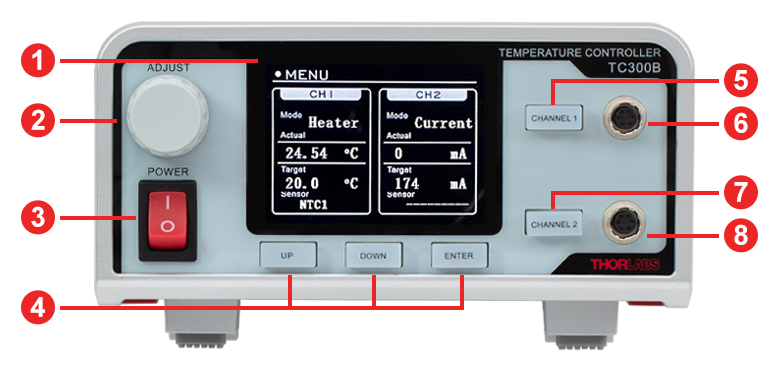
Front Panel
Channel 1 and Channel 2 Hirose Connectors
HR10A-7R-6S(73)
| Callout | Connection | Callout | Connection |
|---|---|---|---|
| 1 | LCD Screen | 5 | Enable/Disable Button for Channel 1 |
| 2 | Adjustment Knob | 6 | Hirose Connector for Channel 1 |
| 3 | Power Switch | 7 | Enable/Disable Button for Channel 2 |
| 4 | Keypads | 8 | Hirose Connector for Channel 2 |
| Pin | Assignment |
|---|---|
| 1 | Heater/TEC Output Positive |
| 2 | Heater/TEC Output Negative |
| 3 | Sensor Positive (4-Wire PT100/PT1000 Only) |
| 4 | Sensor Positive |
| 5 | Sensor Negative |
| 6 | Sensor Negative (4-Wire PT100/PT1000 Only) |
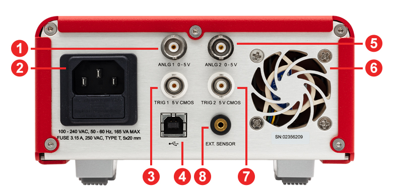
Back Panel
TRIG1 and TRIG2
BNC Female
+5 V CMOS
When set to input: +5 V input will enable the channel, and 0 V input will disable it.
When set to output: outputs +5 V when the channel is enabled and outputs 0 V when the channel is disabled.
ANLG1 and ANLG2
BNC Female
0 to +5 V, 20 kΩ Impedance
Proportional to the actual temperature of the channel; 0 V corresponds to the minimum temperature setting and +5 V corresponds to the maximum temperature setting
| Callout | Connection | Callout | Connection |
|---|---|---|---|
| 1 | Analog Output of Channel 1 (ANLG1) | 5 | Analog Output of Channel 2 (ANLG2) |
| 2 | AC Input Connector | 6 | Cooling Fan |
| 3 | Trigger of Channel 1 (TRIG1) | 7 | Trigger of Channel 2 (TRIG2) |
| 4 | USB Type B Connector | 8 | Mono Jack for External Sensor |
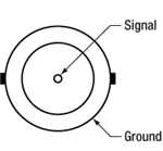
External Sensor Connector
2.5 mm Mono Jack

Accepts 2.5 mm stereo earphone jack. The TC300B controller can support thermistors with resistance up to 999 kΩ.
Computer Connection
USB Type B
USB Type-B Cable Included
The TC300B controller is compatible with thermistors such as the TH10K thermistor as well as PT100 (such as Item # TH100PT) and PT1000 types of Platinum Resistance Temperature Detectors. The following specifications are used for determining the set-point and read back values for these types of thermistors and sensors.
Thermistors
When a thermistor is wired to one of the Hirose connectors on the front panel and the type is set to NTC1 or a thermistor is plugged into the External Sensor port on the back panel and the type is set to EXT1, the TC300B controller measures the resistance value of the thermistor and calculates the temperature based on the “Beta” formulas defined below.R = R0 * eβ[(1/T) - (1/T0)]
R is the resistance in Ω at temperature T
R0 is the nominal resistance in Ω at temperature T0
β is the constant associated with the particular thermistor
T is the temperature in K
T0 is the nominal temperature (usually 298.15 K = 25 °C)
The TC300B controller allows users to set the values of β, R0, and T0. For different thermistors, the actual value of these parameters can vary and can usually be found on their datasheets.
When a thermistor is wired to one of the Hirose connectors on the front panel and the type is set to NTC2 or a thermistor is plugged into the External Sensor port on the back panel and the type is set to EXT2, the TC300B controller also supports the Steinhart-Hart method to approximate the relation between temperature and thermistor resistance, defined by the following formula:
1/T = A + B * ln(R) + C * (ln(R))3
T is the temperature in K
R is the resistance in Ω at temperature T
A, B, and C are Steinhart-Hart parameters
The TC300B controller allows user input of the A, B, and C parameters. For thermistors that support the Steinhart-Hart method, the actual value of A, B, and C can usually be found on their datasheets.
PT100 and PT1000 Sensors
When the sensor type is set to PT100 or PT1000, the TC300B controller measures the resistance and calculates the temperature of the PT100 or PT1000 platinum resistance temperature detector using the following formula:
R = R0 (1 + A * T + B * T2)
(In accordance with IEC 751, 2:1995-07 [DIN EN 60751; 1996-07])
A = 3.9083 x 10⁻³ °C-1
B = -5.775 x 10⁻⁷ °C-2
R is the resistance in Ω at temperature T
T is the temperature in K
R0 = 100 Ω for the PT100
R0 = 1000 Ω for the PT1000
The TC300B controller supports 2- and 4-wire connections for both PT100 and PT1000 sensors. When the sensor type is set to PT100 or PT1000, select the “Parameter” option to toggle between the 2-wire and 4-wire connection setting.

Click to Enlarge
Software GUI
Software
Version 2.0.1
Software package to operate the TC300B including a GUI, drivers, and LabVIEW®/C++/Python SDK for third-party development.
Software for the TC300B Heater and TEC Temperature Controller
Thorlabs provides a software package for the TC300B Heater and TEC Temperature Controller which provides access to all functionality of the controller from a PC interface. After installing the software package and connecting the host PC to the TC300B controller via USB, the PC can control the TC300B controller using either the software GUI or through a command-line interface.
The GUI’s controls duplicate all front-panel functions like setting the sensor parameters, setting the output control scheme (PID, constant current, cycle), and enabling or disabling the output. Additionally, the software allows for data logging of temperature, output current, and output voltage for both channels to a .csv file.
The software GUI and front panel controls are enabled simultaneously (i.e. any adjustments made to the TC300B controller using the front panel are used to update the GUI in real time).
Click to Enlarge
Contents in the Package of the TC300B Heater and TEC Temperature Controller
The following items are included in the TC300B Heater and TEC Temperature Controller package:
- TC300B Heater and TEC Temperature Controller
- Regional Power Cord
- USB Type-B Cable, 2 m (79") Long
- Quick Start Guide
PID Basics
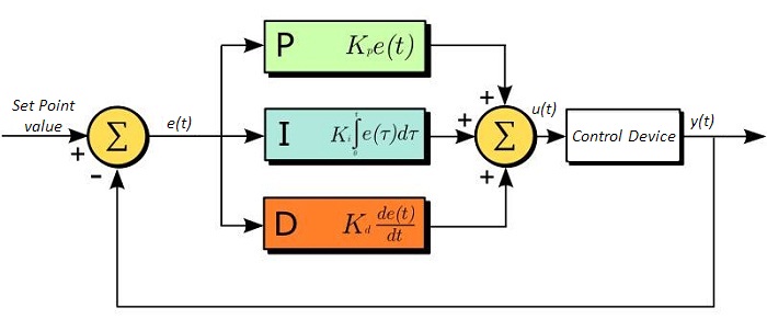
The PID circuit is often utilized as a control loop feedback controller and is commonly used for many forms of servo circuits. The letters making up the acronym PID correspond to Proportional (P), Integral (I), and Derivative (D), which represents the three control settings of a PID circuit. The purpose of any servo circuit is to hold the system at a predetermined value (set point) for long periods of time. The PID circuit actively controls the system so as to hold it at the set point by generating an error signal that is essentially the difference between the set point and the current value. The three controls relate to the time-dependent error signal. At its simplest, this can be thought of as follows: Proportional is dependent upon the present error, Integral is dependent upon the accumulation of past error, and Derivative is the prediction of future error. The results of each of the controls are then fed into a weighted sum, which then adjusts the output of the circuit, u(t). This output is fed into a control device, its value is fed back into the circuit, and the process is allowed to actively stabilize the circuit’s output to reach and hold at the set point value. The block diagram below illustrates the action of a PID circuit. One or more of the controls can be utilized in any servo circuit depending on system demand and requirement (i.e., P, I, PI, PD, or PID).
Through proper setting of the controls in a PID circuit, relatively quick response with minimal overshoot (passing the set point value) and ringing (oscillation about the set point value) can be achieved. Let’s take as an example a temperature servo, such as that for temperature stabilization of a laser diode. The PID circuit will ultimately servo the current to a Thermoelectric Cooler (TEC) (often times through control of the gate voltage on an FET). Under this example, the current is referred to as the Manipulated Variable (MV). A thermistor is used to monitor the temperature of the laser diode, and the voltage over the thermistor is used as the Process Variable (PV). The Set Point (SP) voltage is set to correspond to the desired temperature. The error signal, e(t), is then the difference between the SP and PV. A PID controller will generate the error signal and then change the MV to reach the desired result. For example, if e(t) states that the laser diode is too hot, the circuit will allow more current to flow through the TEC (proportional control). Since proportional control is proportional to e(t), it may not cool the laser diode quickly enough. In that event, the circuit will further increase the amount of current through the TEC (integral control) by looking at the previous errors and adjusting the output to reach the desired value. As the SP is reached (e(t) approaches zero), the circuit will decrease the current through the TEC in anticipation of reaching the SP (derivative control).
Please note that a PID circuit will not guarantee optimal control. Improper setting of the PID controls can cause the circuit to oscillate significantly and lead to instability in control. It is up to the user to properly adjust the PID gains to ensure proper performance.
PID Theory
The output of the PID control circuit, u(t), is given as
where
Kp= Proportional Gain
Ki = Integral Gain
Kd = Derivative Gain
e(t) = SP - PV(t)
From here we can define the control units through their mathematical definition and discuss each in a little more detail. Proportional control is proportional to the error signal; as such, it is a direct response to the error signal generated by the circuit:
Larger proportional gain results in larger changes in response to the error, and thus affects the speed at which the controller can respond to changes in the system. While a high proportional gain can cause a circuit to respond swiftly, too high a value can cause oscillations about the SP value. Too low a value and the circuit cannot efficiently respond to changes in the system.
Integral control goes a step further than proportional gain, as it is proportional to not just the magnitude of the error signal but also the duration of the error.
Integral control is highly effective at increasing the response time of a circuit along with eliminating the steady-state error associated with purely proportional control. In essence integral control sums over the previous error, which was not corrected, and then multiplies that error by Ki to produce the integral response. Thus, for even small sustained error, a large aggregated integral response can be realized. However, due to the fast response of integral control, high gain values can cause significant overshoot of the SP value and lead to oscillation and instability. Too low, and the circuit will be significantly slower in responding to changes in the system.
Derivative control attempts to reduce the overshoot and ringing potential from proportional and integral control. It determines how quickly the circuit is changing over time (by looking at the derivative of the error signal) and multiplies it by Kd to produce the derivative response.
Unlike proportional and integral control, derivative control will slow the response of the circuit. In doing so, it is able to partially compensate for the overshoot as well as damp out any oscillations caused by integral and proportional control. High gain values cause the circuit to respond very slowly and can leave one susceptible to noise and high frequency oscillation (as the circuit becomes too slow to respond quickly). Too low and the circuit is prone to overshooting the SP value. However, in some cases overshooting the SP value by any significant amount must be avoided and thus a higher derivative gain (along with lower proportional gain) can be used. The chart below explains the effects of increasing the gain of any one of the parameters independently.
| Parameter Increased | Rise Time | Overshoot | Settling Time | Steady-State Error | Stability |
|---|---|---|---|---|---|
| Kp | Decrease | Increase | Small Change | Decrease | Degrade |
| Ki | Decrease | Increase | Increase | Decrease Significantly | Degrade |
| Kd | Minor Decrease | Minor Decrease | Minor Decrease | No Effect | Improve (for small Kd) |
Tuning
In general the gains of P, I, and D will need to be adjusted by the user in order to best servo the system. While there is not a static set of rules for what the values should be for any specific system, following the general procedures should help in tuning a circuit to match one’s system and environment. A PID circuit will typically overshoot the SP value slightly and then quickly damp out to reach the SP value.
Manual tuning of the gain settings is the simplest method for setting the PID controls. However, this procedure is done actively (the PID controller turned on and properly attached to the system) and requires some amount of experience to fully integrate. To tune your PID controller manually, first the integral and derivative gains are set to zero. Increase the proportional gain until you observe oscillation in the output. Your proportional gain should then be set to roughly half this value. After the proportional gain is set, increase the integral gain until any offset is corrected for on a time scale appropriate for your system. If you increase this gain too much, you will observe significant overshoot of the SP value and instability in the circuit. Once the integral gain is set, the derivative gain can then be increased. Derivative gain will reduce overshoot and damp the system quickly to the SP value. If you increase the derivative gain too much, you will see large overshoot (due to the circuit being too slow to respond). By playing with the gain settings, you can maximize the performance of your PID circuit, resulting in a circuit that quickly responds to changes in the system and effectively damps out oscillation about the SP value.
| Control Type | Kp | Ki | Kd |
|---|---|---|---|
| P | 0.50 Ku | - | - |
| PI | 0.45 Ku | 1.2 Kp/Pu | - |
| PID | 0.60 Ku | 2 Kp/Pu | KpPu/8 |
While manual tuning can be very effective at setting a PID circuit for your specific system, it does require some amount of experience and understanding of PID circuits and response. The Ziegler-Nichols method for PID tuning offers a bit more structured guide to setting PID values. Again, you’ll want to set the integral and derivative gain to zero. Increase the proportional gain until the circuit starts to oscillate. We will call this gain level Ku. The oscillation will have a period of Pu. Gains for various control circuits are then given to the right in the chart.
Note that when using the Ziegler-Nichols tuning method with some devices like the DSC1 digital servo controller, the integral and derivative terms must be normalized by the sample rate. To do this, the integral term determined from the table should be divided by the sample rate in Hertz and the derivative term should be multiplied by the sample rate in Hertz.
| Posted Comments: | |
Fateme Esmailie
(posted 2025-03-19 16:26:10.257) This device is useless and waste of money as it is very difficult to buy an immersion heater that is compatible with this. cdolbashian
(posted 2025-03-24 03:52:26.0) Thank you for reaching out to us with your concern! We're sorry to hear about your issues with this product. As per our direct communication, we have concluded that our parts are not suitable for your specific application regarding the direct immersion of a heating element into a 4 L volume of water. As our heating elements are not designed for liquid immersion and the controller, due to its listed performance specifications, is unable to provide the necessary heating power for the required thermal load, it was determined that our current offerings were incompatible with your specific application. I have reached out to you to initiate a refund and return of these products. Zehava Bernstein
(posted 2025-02-27 20:26:01.08) I want to know if I can work with this controller with any RTD sensors or only specific sensors that you specify (PT1000).
Are there any sensors that you recommend using? cdolbashian
(posted 2025-03-20 02:08:47.0) Thank you for contacting Thorlabs! The TC300B controller is compatible with both 100 Ω (PT100) and 1000 Ω (PT1000) platinum RTD. The TH100PT we offer is fully compatible with the TC300B controller. (Link: https://www.thorlabs.com/thorproduct.cfm?partnumber=TH100PT). Jongchan Kim
(posted 2024-12-13 17:52:45.76) The TC200 (temperature controller) is not turning on.
Could you please let us know what the possible issues might be?
Also, would it be possible for us to repair it ourselves, or would we need to send it in for service? Pierre Delcrout
(posted 2024-10-09 08:17:02.103) Dear Sir or Mrs,
What is the difference betwween heater and tec mode ?
I want to use it to drive a resistive heater. To freeze the device, the PID should turn off the current as the resitive heater doesn't have a polarity. Contrary to a TEC element, change the sign of the applied current will not cool down the device. It will still genrate heat, no matter the sign of the current. Does it work that way ?
Thank you and best regards
Pierre Delcrout mgarodia
(posted 2024-10-11 12:27:48.0) Thank you for reaching out to us. For the TEC, flipping the direction of the current will change the polarity of the temperature delta between its two surfaces. So, with a correctly designed heat dissipation system it can achieve both, cooling and heating. With the resistive heater, it does not have a polarity, so its functionality is the same regardless of the direction of the current. In heater mode, the TC300B will not change the direction of its output current when the system needs cooling. It will just disable its current output so that the system generates no heat and will be cooled by natural heat dissipation. For the PID control loop of TC300B to work efficiently for heaters, the system needs to be operated at a target temperature that is significantly higher than the ambient temperature so the cooling through natural heat dissipation is efficient enough for the PID loop to react on. Ken Libbrecht
(posted 2024-08-14 10:56:52.173) Excellent product, but the analog output (ANLG1) changes in one-degree increments. Is there any way to get better temperature resolution from this output? cdolbashian
(posted 2024-08-26 09:10:57.0) Thank you for contacting Thorlabs. Unfortunately, due to the limitation of 12bit DAC resolution, the analog output cannot work in higher resolution mode. Adil Meraki
(posted 2024-08-07 11:33:38.387) The user interface is not user-friendly, and its does not provide a pleasant experience with the existing user controls. cdolbashian
(posted 2024-08-14 11:06:28.0) Thank you for your feedback! We highly value the feedback you have put forward and have conveyed it to the R&D department. user
(posted 2024-07-26 19:01:47.767) Hi, I would like to use TC300 with TH10K and HT15W. I set NTC2 because TH10K seem to support the Steinhart-Hart method. But, I got sensor errors. Should I choose NTC1?
(It seemed that TC300 read proper temperature with NTC1 setting.) cdolbashian
(posted 2024-08-01 03:26:53.0) Thank you for contacting Thorlabs. The Standard Steinhart and Hart method are used in TC300 while the ABCD parameters in the TH10K spec sheet are from a variation of the "extended" Steinhart and Hart method. Those two methods follow slightly different mathematic equations thus the parameters are not 100% compatible. We are recommending setting TC300 to NTC1 mode instead of NTC2 when using with TH10K thermistor. user
(posted 2024-03-06 03:34:01.997) I have been using this device TC300 well. Now I am going to use it as a cooler, not a heater. I need some advices. I want to achieve the temperature below -50 degrees Celsius. Is there any way to get the goal? The Peltier device or other device might be the answer in my naive thought, am I right?
Are the TEC(thermoelectric cooler)s kind of the Pelteir devices?
Are the TEC(thermoelectric cooler)s not compatible to TC300?
Please let me know the best combinations for the cooling system that I want if TC300 cannot be used.
My requirements are below.
- the compatibility with TC300
(Actually, the other options are also fine.)
- no external systems
(I want to use it in a normal environment. I mean, I don't want to be hindered by any miscellaneous obstacles. A vacuum facility is also not preferred. Imagine the case of HT24S(Metal Ceramic Heater) connected to TC300.) cdolbashian
(posted 2024-03-15 04:20:59.0) Thank you for contacting Thorlabs. TC300 is compatible with TEC elements. However, the TC300 currently can only drive the TEC as a heater and does not support the cooling function of a TEC. I have contacted you directly to discuss your application further. user
(posted 2024-01-16 13:24:33.88) Dear Sirs
I am interested to build an user programmable hot plate by using your temperature controller TC300 coupled to a ceramic heater. Is it possible to program simple temperature time varying function such as linear ramp (0.5 °C/hour) directly from the front panel or from the thorlabs software? Do you have a manual for the thorlabs software? How does the software work? jdelia
(posted 2024-01-25 12:57:48.0) Thank you for contacting Thorlabs. The TC300's front panel can control the heating elements in heater or current mode. There is a "Sequence” function in the software of the TC300, which can set the temperature value in each step. You can also program this function from TC300 software. The software manual and LabVIEW/C++ /Python SDK example can be found by clicking the "Help" button within the software application. user
(posted 2023-09-22 14:14:36.367) The voltage and current limit does not work. cdolbashian
(posted 2023-10-03 01:13:31.0) Thank you for contacting Thorlabs. We released a new version of the firmware V3.2.5 to downgrade the voltage protection level to warning, so that the TC300 will not disable its output when the overvoltage occurs. You could download the firmware update tool and the latest firmware from the following link https://www.thorlabs.com/software_pages/ViewSoftwarePage.cfm?Code=TC300&viewtab=1.
To update the controller firmware, first please connect the controller to a PC, and keep holding down the “ENTER” button when powering on the device until the device shows "INITIALIZING... Do not Power-off! Updating Now". Secondly please start the firmware update tool, select the correct COM port, and connect. Thirdly please click "Browse" to select the new firmware file. Lastly please click “Update” to start the firmware update. Please note that after the update, the current limit is the still hard limit and over current will disable the device output. user
(posted 2023-08-11 00:03:44.307) Hi Thorlabs,
I expierence a weird issue with the TC300. When i press the channel button to apply voltage, the controller just resets itself. I recorded a video, if it helpfull. Would appreciate your assistance. cdolbashian
(posted 2023-08-16 11:28:25.0) Thank you for contacting Thorlabs. We have reached out to you directly to troubleshoot this further. Michele Cotrufo
(posted 2023-06-19 11:37:03.433) I am using the TC300 together with the TH100PT.
Can you clarify which setting I should use in the TC300 when using this sensor? Can I just pick 'PT100', or should I use a different type/calibration? cdolbashian
(posted 2023-06-23 11:24:56.0) Thank you for reaching out to us with this inquiry. Yes, you can set the sensor type to 'PT100' for TH100PT as it is a 100Ohm platinum resistor. user
(posted 2023-05-12 22:10:28.16) Dear Thorlabs,
I would like to use the TC300 on a new lab laptop with windows 11. Unfortunately the software is only compatible with windows 7 and 10. Are there any possibilities to still use it on windows 11? jdelia
(posted 2023-05-18 11:57:24.0) Thank you for contacting Thorlabs. Per our experience, TC300 software will be fine to work on Win11. We will contact you for some further troubleshooting. user
(posted 2023-01-13 16:34:12.457) Dear Thorlabs Team,
I purchased the TC300 a while ago and am a little dissapointed about its limited usability.
While I understand that its primary application is to drive resistive heaters I do not understand why it does not allow for a negative set temperature. For Example, it is not possible to heat from -200 C to -195 C and keep the temperature stable via the PID. (The current mode is no solution either because it does not read out the temperature. Custom programming with the SDK is also out of the question since I don't have access to a PC at its intended location and it would also defeat the purpose of an integrated PID controller)
Also a big shortcoming is the lack of a "cooling" mode, since you already offer Single-Stage TEC Elements with matching specifications.
Those two things are in my eyes the biggest shortcomings of this device. Otherwise, it would have made for a great and versatile temperature controller with its 6-pin Hirose cable connector. Right now it is "fine".
I hope those shortcomings will be addressed with future firmware updates. jdelia
(posted 2023-01-18 10:26:03.0) Thank you for contacting Thorlabs. At the moment, the TC300 is shipped with the range of the target temperature set to 0 to 200 ⁰C by default. The lower and upper limit of this range can be extended to -200 ⁰C and 400 ⁰C respectively by changing the value of corresponding parameters in the channel setting menu. However, the default PID settings are configured for room temperature applications and thus may not be suitable when the temperature is significantly lower. Users may need to manually fine tune the P, I, and D share value in order to achieve optimum performance. We are working on a new firmware with a new feature of PID auto-tune which could help users to find the best PID settings for their application without the need of lengthy manual tuning. Unfortunately, the current hardware of TC300 does not support cooling by TEC. The development of a new generation of TC300 that are compatible with TECs are already underway. user
(posted 2022-10-24 22:22:28.837) Dear Thorlabs,
I am interested in your TC300 Temperature Controller. I hope control it with Python. Is it possible to control TC300 by Python programming? If possible, could you please offer the example files?
Thanks. cdolbashian
(posted 2022-10-31 01:02:24.0) Thank you for contacting Thorlabs. The software v1.0.0 for the TC300 contains the SDK that supports Python. The SDK manual and example can be found by clicking the "Help" button within the software application. user
(posted 2022-10-07 11:02:00.21) We experience a problem with the TC300 with long-term usage. It switches off the output automatically after about 1 week. Is there a temporal usage limit in the firmware or counters resetting? ksosnowski
(posted 2022-10-10 12:51:40.0) Thank you for contacting Thorlabs. Our TC300 does not have any temporal usage limit or counters. Your local tech support team has reached out directly to you for trouble shooting. Martin Callejo
(posted 2022-08-31 17:52:03.25) Hello,
I would appreciate some technical support.
I'm currently trying to use the TC300 to heat a vapor reference glass cell using a couple of GCH25R thorlabs cap heaters.
I'm having trouble reaching a temperature of 80deg celsius with PID=(0.04, 0.04, 0.0), tau=100ms. The system reaches 77deg and is stable to +-0.01, but the PI control is unable to correct the steady state error of aprox. 3deg.
Increasing P creates oscillations, increasing I above the P value doesn't seem to do nothing.
What are the precise definitions of the PID parameters? Does the PID algorithm have modifications to protect from overshoot?
(i would be nice to include a PID formula in the manual)
Thanks in advance! cdolbashian
(posted 2022-09-07 03:11:21.0) Thank you for contacting Thorlabs. The "P" portion of the PID loop seems appropriate, but the "I" component needs further tuning, considering increase "I" share to decrease the offset. More PID information can be found in the “PID Tutorial” tab (https://www.thorlabs.com/newgrouppage9.cfm?objectgroup_id=14852&tabname=PID%20Tutorial). Additionally, it's worth checking if the current and voltage limits are set correctly to avoid that there is not enough heating power provided by the heating element in combination with TC300 to eliminate the 3 degree offset. And to avoid dissipating too much heat into the environment at higher temperature, a better thermal isolation would be helpful. user
(posted 2022-03-09 15:32:32.593) Is it possible to use the TC300 with TEC elements such as the TECH3S? cdolbashian
(posted 2022-03-11 01:39:19.0) Thank you for contacting Thorlabs. TC300 can drive TECs like TECH3S. At current stage, TC300 can only drive the TEC as a heater and does not support the cooling function of a TEC. TED4015 would be a better choice if you require both active heating and cooling applications. Hyun Gyung Lee
(posted 2022-03-02 19:56:17.17) I'm writing this feedback to get tech support. I bought TC300 to control the temperature of LCC1111T-B. The thing is that we'd like to stabilize the temperature at 70-celsius degrees of LCC1111T-B to make a short response time, BUT it is not working. The error messages, NO LOAD and OVER VOLT, keep popping up. We can only stabilize the temperature at low degrees such as 20-celsius degrees.
Please reply as soon as possible. cdolbashian
(posted 2022-03-04 04:26:01.0) Thank you for contacting Thorlabs. The resistance value of the heater in LCC1111T-B is 38.4Ω. The current applied to the heater should be limited below 600mA to prevent the error of OVER VOLT to be triggered. We will get in touch with you directly to trouble shoot. For future tech support inquiries, please feel free to use our tech support email: techsupport@thorlabs.com. Vladimir Schkolnik
(posted 2022-01-26 15:43:04.41) Hi,
I am very interested in the TC300. I am using two old heaters to regulate the temperature read out by K-Type thermocouples. The required power is only a fraction of the TC300 capabilities, but one part needs to be controlled at a temperature up to 480°C. Is it possible to increase the software limit and display of one channel from 400°C up to this temperature (no increase in current or voltage i needed).
Look forward to hear from you
Best
Vladimir Schkolnik
--------------------------------------
Dr. Vladimir Schkolnik
Project Leader Strontium Activities
Joint Lab Integrated Quantum Sensors
Humboldt-Universität zu Berlin
Institute of Physics
Newtonstraße 15
12489 Berlin
Tel : +49 (0)30 2093 4941 / 7625
Fax : +49 (0)30 2093 4718
vladimir.schkolnik@physik.hu-berlin.de
-------------------------------------- cdolbashian
(posted 2022-02-07 09:19:25.0) Thank you for contacting us Vladimir. In heater mode, the TC300 is able to read temperatures above 400°C from the thermocouple, but cannot set the target temperature above 400°C, limited by the current firmware. In current mode, the temperature can reach 480°C, but the TC300 does not monitor the temperature on the heat load. The actual temperature could rise to a very high level that could cause harm to the heater and become a hazard to personnel. |

 Zoom
Zoom- Heating from -200 °C to 400 °C
- Run Standalone or via Software
- Programmable PID with Auto-Tuning Functionality
The TC300B Heater and Thermoelectric Cooler (TEC) Temperature Controller is a two-channel benchtop controller intended for use with resistive heating elements and thermoelectric cooler devices rated up to 48 W. User-programmable maximum temperature and current/voltage limits protect the connected heating element from being overheated or over driven. Other safety features include an Open Sensor Alarm that will shut down the driver if the temperature sensing element is missing or becomes disconnected.
Capable of standalone operation from a simple keypad interface, this controller can be interfaced with a PC using the included USB Type-B cable with our TC300B Software, LabVIEW® drivers, LabWindows drivers, or using a simple command-line interface from any terminal window.

 Zoom
Zoom
Click to Enlarge
Male Hirose Connector

Click to Enlarge
Wire Diagram
Click to Enlarge
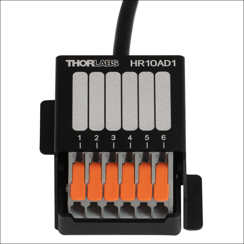
The ports of the HR10AD1 breakout box are labeled with pin numbers. Blank labels are also provided for custom pin assignments.
- Cables with Male 6-Pin Hirose Connectors:
- 3.0 m (9.84') Long Male-to-Male Cable
- 1.8 m (5.90') Long Cable with Breakout Box
- Compatible with Several of Our Products
Thorlabs' HR10CAB1 and HR10AD1 cables feature 6-pin Hirose connectors. The HR10CAB1 cable is 3.0 m (9.84') long and features two male connectors, while the HR10AD1 cable is 1.8 m (5.90') long and features one Hirose connector and one breakout box for connecting loose wires without the need for soldering.
These cables are compatible with our TC300B heater temperature controller, and the breakout box can be used to easily connect a custom combination of resistive heaters and thermistors, as shown in the image to the right. The HR10CAB1 cable can be used to connect an SH05R(/M) or SH1(/M) beam shutter to an SC10 shutter controller or KSC101 K-Cube solenoid controller.
If a custom soldered connection is required, these Hirose connector cables can also be cut to any length, leaving one connectorized end and one bare end. The colored wire diagram above shows the relationship between the six colored wires and the pins in the connector, allowing the cut cable to be incorporated into a variety of custom applications where the breakout box is unsuitable. Note that the wires in these cables cross over the length of the cable, so the insulation color should be used for pin identification.
The ports of the HR10AD1 breakout box are each labeled with the pin number corresponding to the male Hirose connector, as shown in the image to the left. In addition, blank labels are provided next to each pin number for custom pin assignment information to be added. A graphite pencil is recommended for filling in the blank labels, as the markings can be removed using a standard rubber eraser if the pin assignments are changed.