 Products Home
SAF Gain Chips on Submounts
- InP or GaAs Gain Chips on Submount or Submount with Heatsink
- Ultra-Low Reflectance at Angled Facet
- Custom Coatings Available
SAF795C
Single Angle Facet Gain Chip on Submount (800 nm)
SAF1091H
Single Angle Facet Gain Chip on Submount with Heat Sink (1650 nm)
SAF Gain Chips are Available with Either Low- or High-Reflectivity Coatings on the Normal Facet (R2) to Support a Wide Range of External Cavity Configurations


Please Wait
| SAF Gain Chips |
|---|
| Chip in Ø9 mm TO Can |
| 780, 840, and 1040 nm CWL |
| Half-Butterfly Assembly |
| CWLs from 1220 nm to 1900 nm |
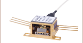
| Chip on Submount |
| CWLs from 800 nm to 1650 nm |
| Webpage Features | |
|---|---|
| Clicking this info icon below will open a window that contains item specifications and graphs. | |
Features

Click to Enlarge
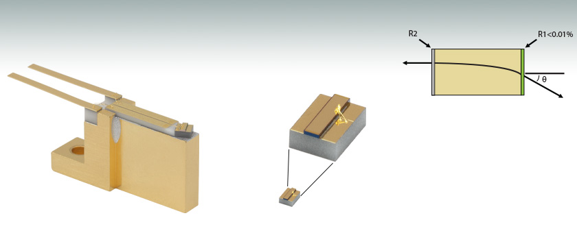
Figure 1.1 Enlarged View of SAF795H Gain Chip on Submount with Heat Sink.
- Broad Tuning Range
- High Output Power
- Ultra-Low Angled Facet Reflectance: 0.005% (Typ.)
- Gain Medium for Narrow Linewidth Fiber Bragg Grating Lasers
- Gain Medium for Widely Tunable External Cavity Semiconductor Lasers
Single Angled Facet (SAF) gain chips use a geometric technique to further reduce the reflection on one end of the chip by curving the ridge waveguide so that it is not normally incident to the chip facet. This, in combination with an AR coating on that facet, virtually eliminates back reflections that can create unwanted feedback into the laser cavity. As a result, SAF gain chips are superior to standard gain chips when used in Extended Cavity Lasers (ECLs), particularly tunable ECLs, since any residual reflection from the AR-coated Fabry-Perot (FP) gain chip facet often limits the stability, output power, and spectral quality of the laser.
Thorlabs offers SAF gain chips with either low- or high-reflectivity coatings on the normal facet to support a wide range of external cavity configurations. For more information on the importance of normal facet reflectivity in these configurations, please see the ECL Tutorial tab. For sample results of SAF gain chips in external cavity laser setups suited to both low- and high-reflectivity coatings, please refer to the ECL Sample Results tab. Our SAF gain chips are available either on submounts alone or on submounts with a heatsink and cathode/anode leads attached.
Handling and Usage
These SAF gain chips are sensitive to electrostatic shock, they should always be handled using standard static avoidance practices.
These SAF gain chips are not intended to be used as Amplified Spontaneous Emission (ASE) sources as this will significantly decrease their lifetime. For more information on using the SAF gain chip in an external cavity laser, see the ECL Tutorial tab.
External Cavity Diode (ECL) Lasers: Tunable Wavelength and Narrow Bandwidth
Two elements are required for a laser to operate: (1) an active gain medium that amplifies the optical signal and (2) a feedback mechanism to provide sustained laser oscillation. In a Fabry-Perot laser, two mirrors, having reflection coefficients of r1 and r2 (power reflectance R1 = r12 and R2 = r22), respectively, provide feedback for the optical field, as shown in Figure 41A.
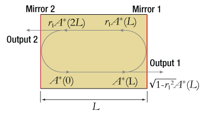
Figure 41A Fabry-Perot Laser Structure
The round-trip gain for the optical field within a cavity of length L can be expressed as:

where g and αi are the gain and internal loss coefficients, respectively, λ is the vacuum wavelength, neff is the effective refractive index, and L is the cavity length. Solving for unity results in the threshold amplitude (Eq. 2) and phase (Eq. 3) conditions:
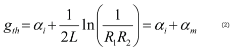

where αm is defined as the mirror loss and N is a running integer index representing the mode number.
In a semiconductor (diode) laser, the gain medium is excited by injecting a current into the junction region of a forward-biased diode. The high concentration of electrons and holes in the engineered quantum-well junction of a semiconductor laser makes it possible to create the population inversion required for optical gain.
When the gain medium is a semiconductor material, a Fabry-Perot cavity can be created by the Fresnel optical reflections at the cleaved facets of the chip. The junction is effectively a waveguide that extends from one facet to the other. An uncoated "as-cleaved" facet perpendicular to the waveguide has a reflectivity of R ~ 30%. However, the maximum output power of the device can be optimized by modifying the reflectance of the facets with optical coatings. Maximum power for a Fabry-Perot laser diode is typically achieved with a high-reflectivity (HR) coating on the back facet and a low-reflectivity (LR) coating on the front facet.
The emission spectrum of the Fabry-Perot laser diode device will be dependent on the injection current. When biased below threshold with g > αi , the emission spectrum consists of a broad series of peaks corresponding to the longitudinal modes of the Fabry-Perot cavity defined by the phase equation. Lasing does not occur until the injection current is increased to the point where g = αi + αm. The lasing wavelength is determined by the longitudinal mode that first achieves the threshold condition. The output spectrum does not always collapse into a single lasing wavelength but can consist of a narrow spectrum of longitudinal modes.

Figure 41B Gain Curve of a Fabry-Perot Laser
This is particularly true for InP-based Fabry-Perot lasers, which typically have an optical bandwidth of 5 to 10 nm. GaAs-based devices can operate in a single longitudinal mode, depending on wavelength and output power. They typically have an output bandwidth <2 nm.
A typical 850 nm laser diode with a length of around 300 µm and a group index around 4 will have a longitudinal mode spacing of 0.3 nm, which is similar to a 1 mm long 1550 nm laser diode. Changing the length or refractive index of the cavity, for example by heating or cooling the laser diode, will shift the whole comb of modes and consequently the output wavelength.
Laser Linewidth
The linewidth of a semiconductor laser single longitudinal lasing mode (FWHM) is given by the Schawlow-Townes-Henry Laser Linewidth equation, a modified Schawlow and Townes formula that incorporates the Henry linewidth enhancement factor αH [1]:
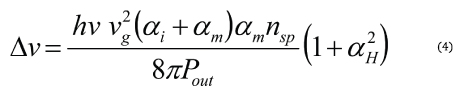
where hv is the photon energy, vg is the group velocity, nsp is the population inversion factor, and Pout is the single-facet output power. This equation describes the spectral broadening of the laser linewidth due to phase and amplitude fluctuations caused by the unavoidable addition of spontaneous emission photons to the coherent lasing mode. These so-called quantum noise fluctuations define a lower limit on the laser linewidth, which may be masked by larger noise fluctuations caused by mechanical/acoustic vibration or thermal variation.
Extending the length of the cavity will decrease αm (see Eq. 2), which reduces the linewidth. This can be understood by viewing the quantum noise-limited linewidth (see Eq. 4) as being proportional to the ratio of the number of spontaneous emission photons in the lasing mode. Increasing the cavity length both reduces the number of spontaneous emission photons (by decreasing the "cold-cavity" spectral width of each longitudinal mode) and increases the total number of photons in the cavity for a fixed output power. This is why the cavity length term appears twice in the Schallow-Townes equation.
A single-frequency distributed feedback (DFB) diode laser with cavity of 0.3 mm will typically have an emission linewidth on the order of 1 to 10 MHz. Increasing the length of the cavity to 3 cm, for example, will narrow the emission linewidth by a factor of more than 100. It has been shown [2] that the linewidth of the emission from an extended cavity semiconductor lasers can be reduced to <1 kHz.
Single Wavelength Operation and Tuning
For many applications, it is desirable to have a single longitudinal mode (single frequency) laser, to be able to adjust the lasing wavelength, or both. To accomplish this, a wavelength-selective feedback element external to the semiconductor laser chip can be used to select the lasing wavelength. Proper operation of this external cavity laser (ECL) requires suppression of the intrinsic optical feedback from the semiconductor chip Fabry-Perot cavity so that it does not interfere with the external feedback. The gain chip's Fabry-Perot cavity effect can be reduced by applying an antireflection (AR) optical coating to one chip facet.
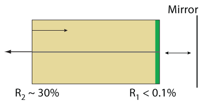
Figure 41C External Cavity Operation Based on a Gain Chip
At a minimum, the chip facet reflectance (R1) should be 20 dB less than the external feedback (Rext); that is, R1 < 10-2 x Rext [3]. Even with the AR coating, the residual reflection from the AR-coated Fabry-Perot gain chip facet often limits the stability, output power, and spectral quality of the ECL, especially if the laser is tunable. To further reduce the reflection at the chip facet, the combination of an angled waveguide and an AR coating can be used to effectively remove most of the feedback from the internal chip Fabry-Perot cavity [4]. This single-angled-facet (SAF) gain chip provides a superior structure for ECLs, in particular broadband tunable ECLs.
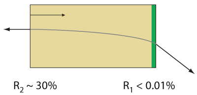
Figure 41D Single-Angled-Facet Gain Chip
External Cavity Laser Design
There are numerous approaches for implementing an external cavity semiconductor laser [3]. The first consideration for most approaches is the choice of a wavelength-selective feedback element. One of the most common feedback elements is a diffraction grating, which can be used as the feedback element in both single-frequency and broadly tunable external cavity lasers.
When the collimated output of the gain chip is incident on a diffraction grating at angle θ with respect to the grating surface normal and perpendicular to the grating lines, the diffracted beams exit the grating at an angle θ' determined by the grating equation:
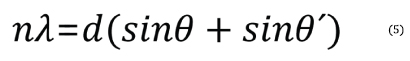
Here, n is the order of diffraction, λ is the diffracted wavelength, and d is the grating constant (the distance between grooves). For n > 0, the diffraction grating will spatially separate a polychromatic incident beam by diffracting the beam at an angle θ', which is wavelength dependent. Once the spectral content of the gain chip is spatially separated, a variety of means can be employed to selectively reflect light with a specific wavelength back into the gain medium.
Littrow ECL Configuration
One of the simplest approaches is to use a Littrow configuration where the diffraction grating is oriented so that the first-order diffraction is retroreflected back into the gain chip (i.e., θ = θ' in Eq. 5):

The laser output power can be taken from the zero-order reflection of the grating, which is often done because it minimizes the number of optical elements required to construct the ECL (a collimating lens and the diffraction grating).
Wavelength tuning is accomplished by rotating the diffraction grating, which varies the wavelength of light that is reflected back into the waveguide. When the diffraction grating (grating constant), collimation lens, and cavity length are chosen so that only one longitudinal mode is reflected back to the gain chip within the acceptance angle of the waveguide, the external cavity laser will produce a signle frequency laser spectrum. Note that the selection of collimation lens is important because it affects the amount of grating area that is illuminated as well as the focused spot size coupling back into the semiconductor gain chip. One of the disadvantages of this configuration is that the angle of the zero-order output beam changes as the wavelength is tuned. However, this problem can be avoided if the output of the ECL is emitted from the normal facet of the SAF gain chip. In this configuration, the reflectance of the SAF normal facet is typically reduced to R ~ 10% and a grating is chosen that efficiently diffracts light into the order being used to create the ECL to maximize the output power of the laser.
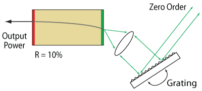
Figure 41E Littrow External Cavity Laser
Littman-Metcalf ECL Configuration
Another common ECL implementation is the Littman-Metcalf configuration, which uses an additional adjustable mirror to select the feedback wavelength [5]. The double-pass of the diffraction grating at an increased angle of incidence results in an external cavity that has better wavelength selectivity. As a result, the output beam of a Littman-Metcalf ECL typically as a narrower linewidth than a similar laser built using a Littrow configuration. In the Littman-Metcalf configuration, the output beam of the laser is typically the zero-order reflection from the diffraction grating, since the propagation direction remains fixed as the wavelength is tuned. In this case, the SAF normal facet is coated with a high-reflective (HR) coating, typically >90%, in order to minimize the losses in the ECL, which maximizes the output power.
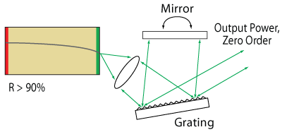
Figure 41F Littman-Metcalf External Cavity Laser
For some applications it may still be desirable to use the normal facet of the SAF chip as the output coupler of the laser. For these applications, a low reflection coating on the normal facet of the SAF gain chip would be required in order to maximize the output power of the laser.
One drawback to the Littman-Metcalf design is that the internal losses are higher than in the Littrow configuration, and hence, the output power of the laser is typically lower. The increase in internal losses are mainly due to the loss of the zero-order beam reflected from the tuning mirror and the increased loss due to the decrease in the efficiency of the grating when used to reflect light at a large angle of incidence.
Innovative ECL Design
The innovative design of an SAF gain chip is ideal for use in external cavity lasers because it virtually eliminates the unwanted feedback from the intracavity facet of the gain chip. Thorlabs offers SAF chips with both low- and high-reflectivity coatings on the normal facet in order to support a wide variety of external cavity configurations. For information on custom coatings that optimize the performance of a particular external cavity laser configuration, please contact Tech Support.
References
(1) Henry, C. H., "Theory of the Linewidth of Semiconductor Lasers." IEEE J. of Quantum Electron QE-18, 259 (1982).
(2) Wyatt, R., Cameron, K. H., and Matthews, M. R. "Tunable Narrow Line External Cavity Lasers for Coherent Optical Communication Systems." Br. Telecom. Technol. J. 3, 5 (1985).
(3) Zorabedian, P. "Tunable External Cavity Semiconductor Lasers." Tunable Lasers Handbook Ed. Duarte, F. J. New York, Academic, 1995. Chapter 8.
(4) Heim, P. J. S., Fan, Z. F., Cho, S.-H., Nam, K., Dagenais, M., Johnson, F. G., and Leavitt, R. "Single-angled-facet Laser Diode for Widely Tunable External Cavity Semiconductor Lasers with High Spectral Purity." Electron. Lett. 33, 1387 (1997).
(5) Littman, M. G. and Metcalf, H. J. "Spectrally narrow pulsed dye laser without beam expander." Appl. Opt. 17, 2224 (1978).
Sample Results of an SAF1093C Used in a Basic Littrow Configuration
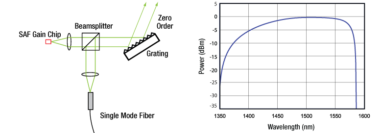
Figure 3.1 Sample power spectrum generated by an SAF1093C gain chip in an external cavity laser. A Littrow configuration, as shown in the diagram, was used for the external cavity design due to the SAF1093C’s high normal facet reflectivity of 90%. For more information on this configuration and the use of gain chips in external cavity lasers, please refer to the ECL Tutorial tab.
Sample Results of an SAF1144C Used in a Basic Littman-Metcalf Configuration
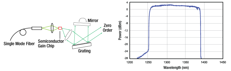
Figure 3.2 Sample power spectrum generated by an SAF1144C gain chip in an external cavity laser. A Littman-Metcalf configuration, as shown in the diagram, was used for the external cavity design due to the SAF1144C's low normal facet reflectivity of 10%. For more information on this configuration and the use of gain chips in external cavity lasers, please refer to the ECL Tutorial tab.

Click to Enlarge
Figure 4.1 Diagram of the anode and cathode pins of SAF gain chip on submount. Please note that dimensions of chip vary depending on item #.

Click to Enlarge
Figure 4.2 Diagram of the anode and cathode Pins of SAF gain chip on submount with heat sink. Please note that dimensions of chip vary depending on item #.
| Posted Comments: | |
| No Comments Posted |
Click the ![]() icon below for more detailed performance specifications.
icon below for more detailed performance specifications.
| Table G1.1 Key Specificationsa,b | |||||||
|---|---|---|---|---|---|---|---|
| Item # | Info | ASE Center Wavelength | Optical Bandwidthc,d | ASE Powerd | Normal Facet Reflectivity | Lateral Beam Exit Angle | Operating Current (Typ./Max) |
| SAF795C | 800 nm | 12 nm | 55 mW | 90% | 19.5° | 250 mA/300 mA | |
| SAF815C | 815 nm | 13 nm | 50 mW | 90% | 19.5° | 250 mA/300 mA | |
| SAF852C | 853 nm | 10 nm | 95 mW | 90% | 19.5° | 250 mA/300 mA | |
| SAF1064C | 1080 nm | 25 nm | 120 mW | 90% | 19.5° | 400 mA/450 mA | |
| SAF1145C | 1220 nm | 80 nm | 1.0 mW | 10% | 26.5° | 300 mA/500 mA | |
| SAF1144C | 1320 nm | 50 nm | 20 mW | 10% | 26.5° | 600 mA/800 mA | |
| SAF1093C | 1450 nm | 95 nm | 20 mW | 90% | 26.5° | 500 mA/800 mA | |
| SAF1126Ce | 1517 nm | 75 nm | 0.5 mW | 10% | 19.5° | 300 mA/350 mA | |
| SAF1118Ce | 1573 nm | 79 nm | 1.7 mW | 10% | 19.5° | 300 mA/350 mA | |
| SAF1091C | 1650 nm | 90 nm | 1.3 mW | 90% | 26.5° | 500 mA/800 mA | |
- Specifications are given at a chip temperature TChip = 25 °C. All quoted values are typical, unless otherwise indicated.
- These Single Active Facet (SAF) gain chips are meant to be used in external cavity lasers. Product lifetime will be significantly reduced by using it in an Amplified Spontaneous Emission mode.
- Specified as the Width of the ASE Spectrum 3 dB Below the Peak
- Specified at Operating Current (Typ.)
- Specifications for gain chip in a Littrow external cavity configuration available by clicking the
 icon.
icon.
Click the ![]() icon for more detailed performance specifications.
icon for more detailed performance specifications.
| Table G2.1 Key Specificationsa,b | |||||||
|---|---|---|---|---|---|---|---|
| Item # | Info | ASE Center Wavelength | Optical Bandwidthc,d | ASE Powerd | Normal Facet Reflectivity | Lateral Beam Exit Angle | Operating Current (Typ./Max) |
| SAF795H | 800 nm | 12 nm | 55 mW | 90% | 19.5° | 250 mA/300 mA | |
| SAF815H | 815 nm | 13 nm | 50 mW | 90% | 19.5° | 250 mA/300 mA | |
| SAF852H | 853 nm | 10 nm | 95 mW | 90% | 19.5° | 250 mA/300 mA | |
| SAF1064H | 1080 nm | 25 nm | 120 mW | 90% | 19.5° | 400 mA/450 mA | |
| SAF1145H | 1220 nm | 80 nm | 1.0 mW | 10% | 26.5° | 300 mA/500 mA | |
| SAF1144H | 1320 nm | 50 nm | 20 mW | 10% | 26.5° | 600 mA/800 mA | |
| SAF1093H | 1450 nm | 95 nm | 20 mW | 90% | 26.5° | 500 mA/800 mA | |
| SAF1126He | 1517 nm | 75 nm | 0.5 mW | 10% | 19.5° | 300 mA/350 mA | |
| SAF1118He | 1573 nm | 79 nm | 1.7 mW | 10% | 19.5° | 300 mA/350 mA | |
| SAF1091H | 1650 nm | 90 nm | 1.3 mW | 90% | 19.5° | 500 mA/800 mA | |
- Specifications are given at a chip temperature TChip = 25 °C. All quoted values are typical, unless otherwise indicated.
- These Single Active Facet (SAF) gain chips are meant to be used in external cavity lasers. Product lifetime will be significantly reduced by using it in an Amplified Spontaneous Emission mode.
- Specified as the Width of the ASE Spectrum 3 dB Below the Peak
- Specified at Operating Current (Typ.)
- Specifications for gain chip in a Littrow external cavity configuration available by clicking the icon.