 Products Home
LED Ring Light Sources

- LED Ring Lights with Ø0.99" Clear Aperture
- Array of 40 High Brightness LEDs
- Compatible with Thorlabs' LED Drivers
- Central Wavelengths from 470 to 850 nm and a Broadband White Option Available
LEDRW40
Ø0.99" Clear Aperture
LED Ring Light
Application Idea
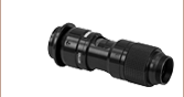
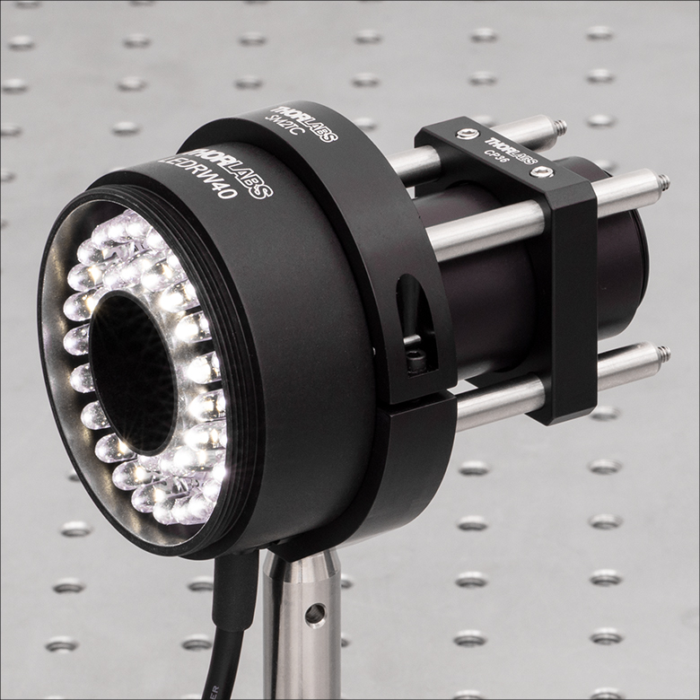
The LED Ring Lights can be post-mounted using an SM2TC Clamp.


Please Wait
Click to Enlarge
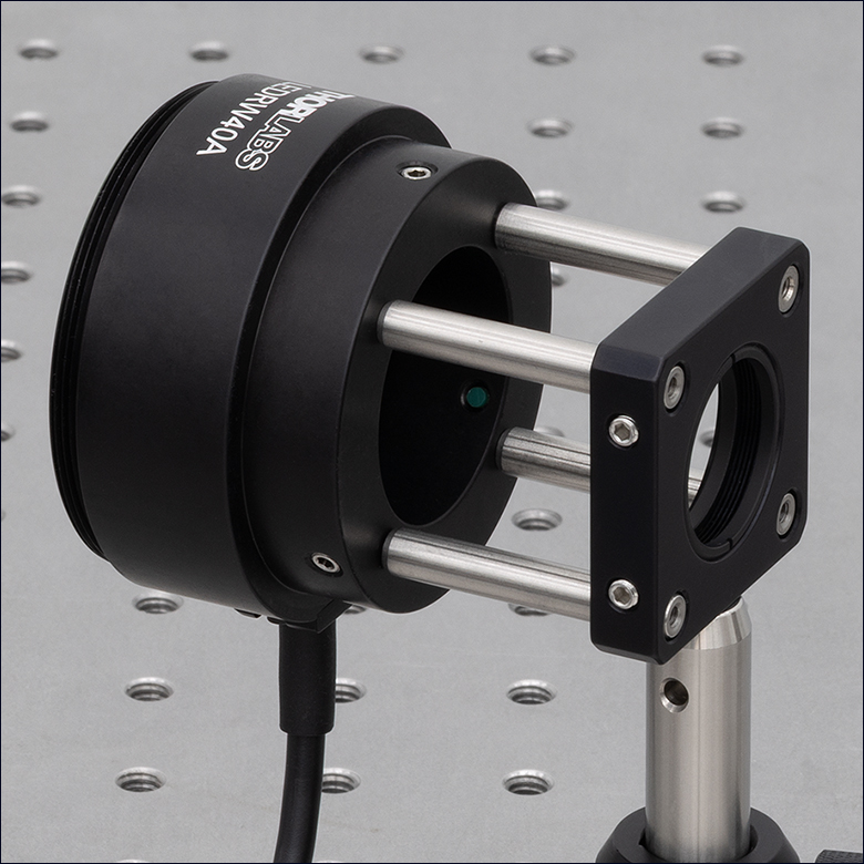
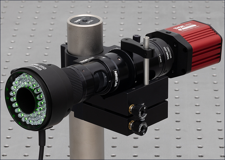
Figure 1.2 The LED Ring Lights can be integrated into a 30 mm cage system as seen above.
Click to Enlarge
Figure 1.1 The LED Ring Lights can be post-mounted using an SM2TC clamp.
Click to Enlarge
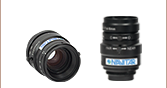
Figure 1.3 The LED Ring Lights have three nylon-tipped setscrews to interface with zoom lenses such as the MVL6X12Z.
Features
- LED Ring Arrays Composed of 40 High Brightness LEDs
- 4 Central Wavelengths from 470 nm to 850 nm, 1 Broadband White Option Available
- Ø0.99" (Ø25.1 mm) Clear Aperture
- 50 - 300 mm Optimal Working Distance
- Compatible with Our 30 mm Cage System
- Integrated Memory (EEPROM) Stores LED Operating Parameters
- Integrated M8 Connector for use with Thorlabs' LED Drivers
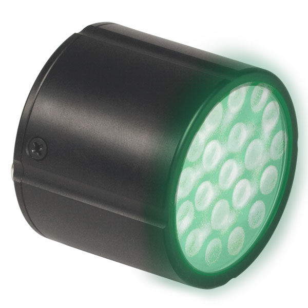
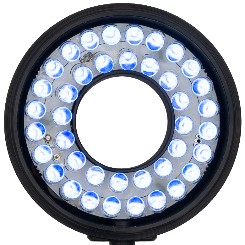
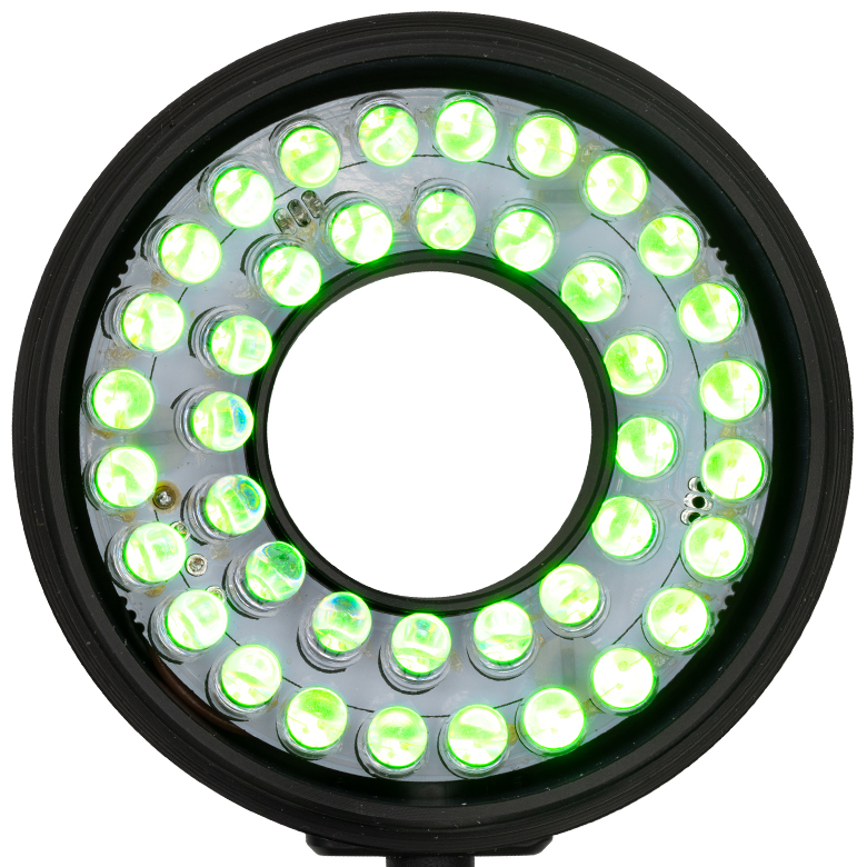
Thorlabs' LED Ring Light Sources consist of 40 individual LEDs in a ring-shaped array with a Ø0.99" (Ø25.1 mm) clear aperture. The LEDs are angled to provide illumination across a working distance of 50 mm to 300 mm along the emission axis and act as a bright field lighting source. The central aperture enables unobstructed viewing or imaging through the light sources, making them an ideal choice for machine vision, inspection systems, and other camera-based applications.
Constructed from anodized aluminum, these LED ring light housings feature four 4-40 tapped holes that are compatible with our Ø6 mm ER cage rods, allowing for integration with 30 mm cage systems. The housings also feature three setscrews on the sides for interfacing with Ø1" Lens Tubes and various camera lenses and high-magnification zoom lens systems (as seen in Figure 1.3), which can be secured using a 5/64" (2.0 mm) hex key or balldriver. The backs of the ring lights have the same Ø2.20" outer diameter as a Ø2" Lens Tube, allowing them to fit inside Ø2" Lens Tube Mounts. An M60 x 1.0 external thread at the head of the ring light gives the option of attaching various elements such as custom filters or diffusers.
For convenient connection to the drivers listed below and on the LED Drivers tab, the LED ring lights have a connection cable with an M8 connector; see the Pin Diagram tab for the M8 connector pin information. These LED ring lights also feature an EEPROM chip which stores information about the LED (e.g., current limit, forward voltage). When controlled by a Thorlabs LED driver designed to read the EEPROM chip, the data can be used to implement smart safety features.
Driver Options
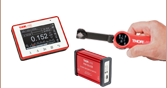
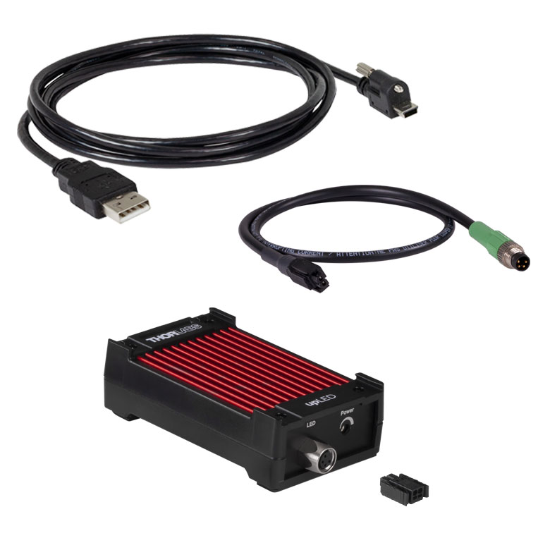
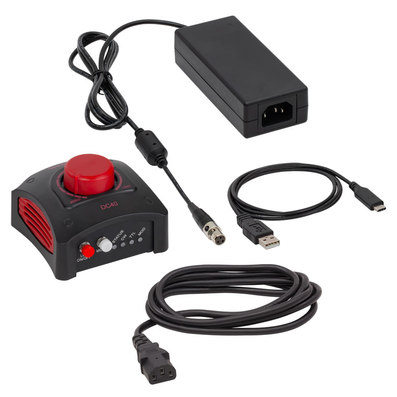
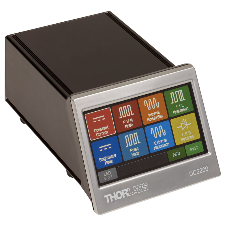
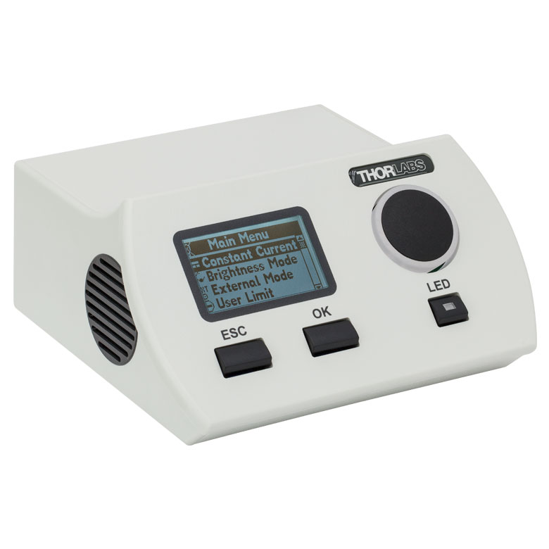
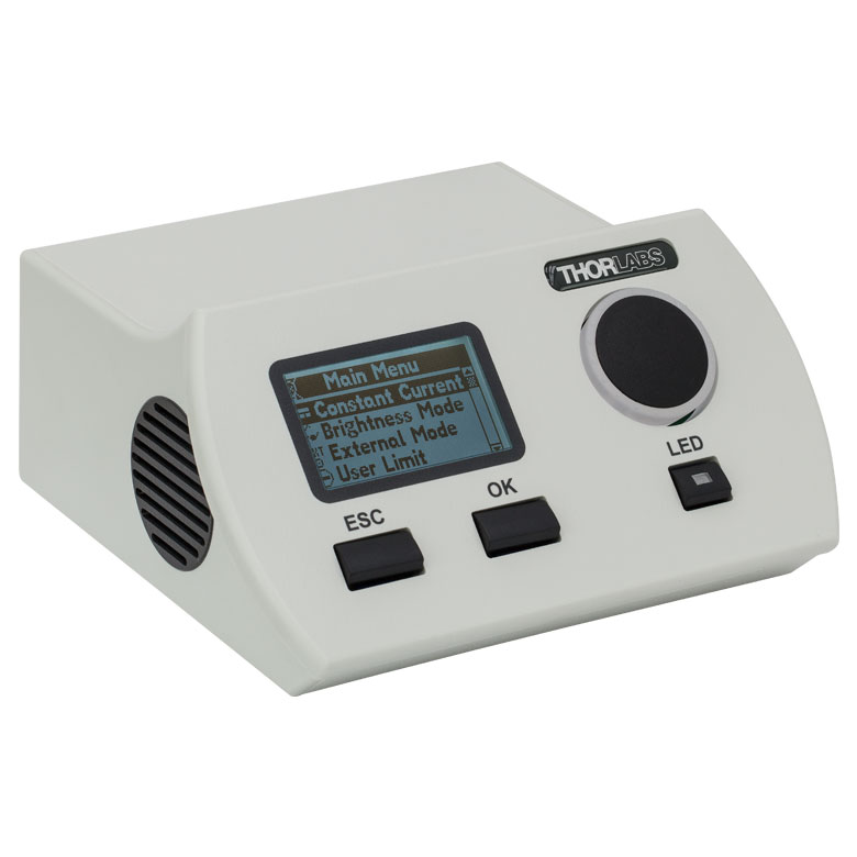
Thorlabs offers six drivers compatible with some or all these LED ring lights: LEDD1B, DC40, UPLED, DC2200, DC4100, and DC4104 (the latter two require the DC4100-HUB). See Table G1.1 for driver compatibility information, and the LED Drivers tab for a list of specifications. The UPLED, DC40, DC2200, DC4100, and DC4104 drivers are capable of reading the current limit from the EEPROM chip of the connected LED ring light and automatically adjusting the maximum current setting to protect the LEDs. The DC40 LED driver can provide drive currents with up to a 5 kHz modulation when supplied with an external modulation signal. While the DC2200, DC4100, and DC4104 drivers are capable of modulating much higher frequencies, these ring lights are not approved for modulation at or above 9 kHz.
Please note that these LED ring lights are not intended for use in household illumination applications.
Thorlabs also offers a range of unmounted, mounted, collimated, and fiber-coupled LEDs that are designed for a variety of applications, including microscopy, illumination, and measurements. For questions on choosing an appropriate LED and to discuss mounting requirements, please contact Tech Sales.
| Pin | Specification | Wire Color |
|---|---|---|
| 1 | LED Anode | Brown |
| 2 | LED Cathode | White |
| 3 | EEPROM GND | Black |
| 4 | EEPROM IO | Blue |

Figure 2.1 Pin Diagram
Pin Connection - Male
Figure 2.1 shows the male connector of the LED Ring Lights. It is a standard M8 x 1.0 sensor circular connector. Pins 1 and 2 are the connection to the LED. Pin 3 and 4 are used for the internal EEPROM. If using an LED driver that was not purchased from Thorlabs, be careful that the appropriate connections are made to Pin 1 and Pin 2 and that you do not attempt to drive the LED through the EEPROM pins.
To fully support the max optical power of the LED you intend to drive, ensure that the max voltage and max current of the driver are equal to or greater than those of the LED.
| Compatible Drivers | LEDD1B | UPLEDa | DC40a | DC2200a | DC4100a,b | DC4104a,b |
|---|---|---|---|---|---|---|
| Click Photos to Enlarge | 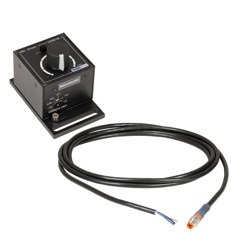 |
 |
 |
 |
 |
 |
| LED Driver Current Output (Max)c | 1.2 A | 1.2 A | 4.0 Ad | LED1 Terminal: 10.0 A LED2 Terminal: 2.0 Ae |
1.0 A per Channel | 1.0 A per Channel |
| LED Driver Forward Voltage (Max)f | 12 V | 8 V | 14.0 Vd | 50 V | 5 V | 5 V |
| Modulation Frequency Using External Input (Max) | 5 kHz | - | 5 kHz | 250 kHzg,h | 100 kHzh (Simultaneous Across all Channels) |
100 kHzh (Independently Controlled Channels) |
| External Control Interface(s) | Analog (BNC) | USB 2.0 | USB 2.0, TTL, and Analog (BNC) | USB 2.0 and Analog (BNC) | USB 2.0 and Analog (BNC) | USB 2.0 and Analog (8-Pin) |
| Main Driver Features | Very Compact Footprint 60 mm x 73 mm x 104 mm (W x H x D) |
USB-Controlled | Driver Current Up to 4.0 A, Manual and USB-Controlled |
Touchscreen Interface with Internal and External Options for Pulsed and Modulated LED Operation | 4 Channelsb | 4 Channelsb |
| EEPROM Compatible: Reads Out LED Data for LED Settings | - | |||||
| LCD Display | - | - | - | |||
| Compatible Ring Lights | LEDRW40, LEDRW40A, LEDRW40B, LEDRW40C, LEDRW40Di | LEDRW40, LEDRW40A, LEDRW40B, LEDRW40C, LEDRW40D | LEDRW40C, LEDRW40Di | |||
| Posted Comments: | |
| No Comments Posted |
This tab includes all LEDs sold by Thorlabs. Click on More [+] to view all available wavelengths for each type of LED pictured below.
| Light Emitting Diode (LED) Selection Guide | ||||||
|---|---|---|---|---|---|---|
| Click Photo to Enlarge (Representative; Not to Scale) |
 |
 |
 |
 |
 |
 |
| Type | Unmounted LEDs | Pigtailed LEDs | LEDs in SMT Packages |
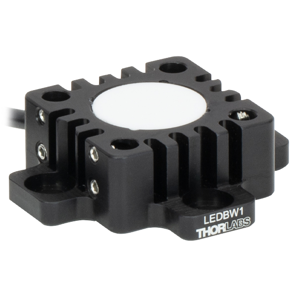
LED Arrays | LED Ring Light | Cage-Compatible Diffuse Backlight LED |
| Light Emitting Diode (LED) Selection Guide | ||||||
|---|---|---|---|---|---|---|
| Click Photo to Enlarge (Representative; Not to Scale) |
 |
 |
 |
 |
 |
 |
| Type | PCB- Mounted LEDs |
Heatsink- Mounted LEDs |
Collimated LEDs for Microscopyb | Fiber- Coupled LEDsc |
High-Power LEDs for Microscopy | Multi-Wavelength LED Source Optionsd |
| Table G1.1 Specificationsa | |||||
|---|---|---|---|---|---|
| Item # | LEDRW40A | LEDRW40B | LEDRW40C | LEDRW40D | LEDRW40 |
| LED Power Outputb,c | ≥550 mW (Typ. 800 mW) |
≥215 mW (Typ. 320 mW) |
≥280 mW (Typ. 415 mW) |
≥730 mW (Typ. 1170 mW) |
≥370 mW (Typ. 540 mW) |
| Forward Voltageb,c | 6.4 V | 6.4 V | 4.2 V | 3.5 V | 6.4 V |
| Maximum Irradiance at 75 mmb,c,d | 500 µW/mm2 | 210 µW/mm2 | 335 µW/mm2 | 310 µW/mm2 | 310 µW/mm2 |
| Maximum Irradiance at 200 mmb,c,d | 165 µW/mm2 | 55 µW/mm2 | 75 µW/mm2 | 70 µW/mm2 | 88 µW/mm2 |
| General Specifications | |||||
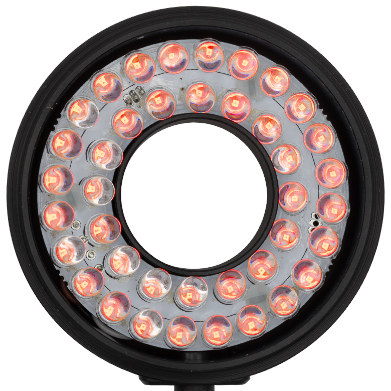
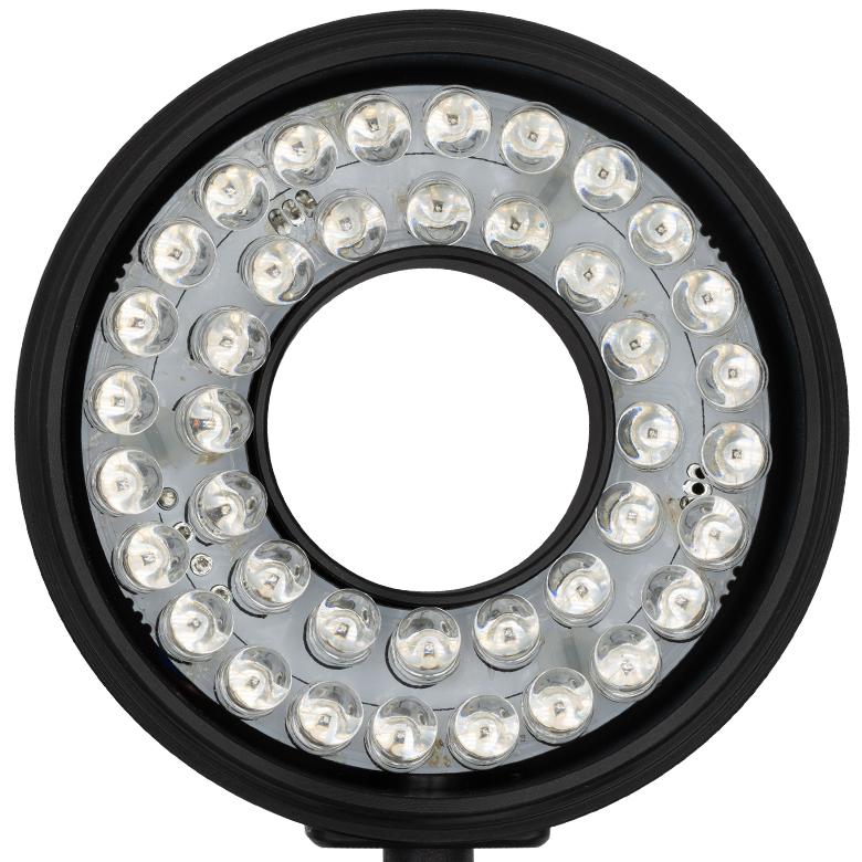
| Color Imagee (Click to Enlarge) |
 |
 |
 |
 |
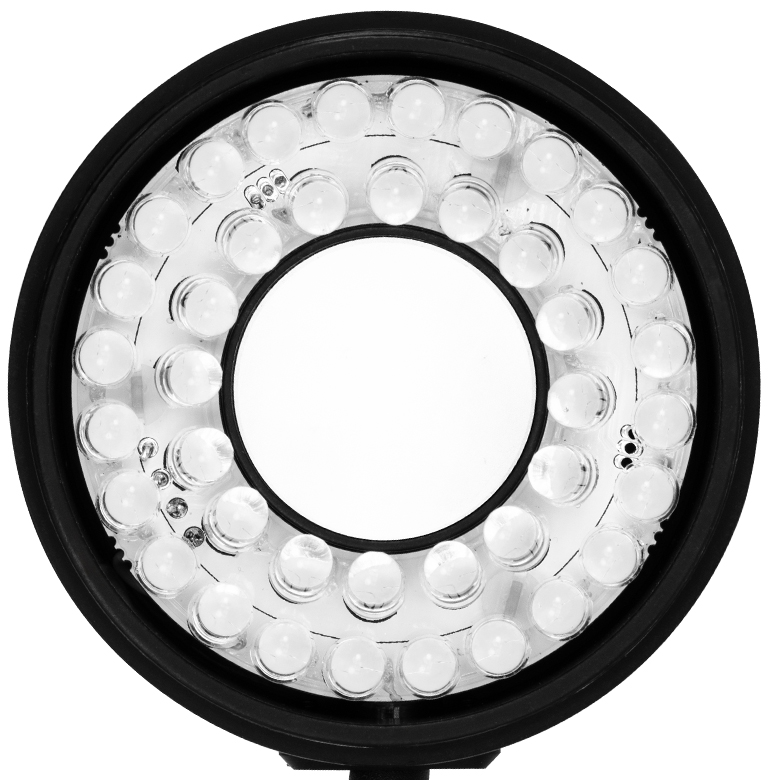 |
| Color | Blue | Green | Red | Infrared (IR) | Daylight White |
| Central Wavelengthf | 470 nm | 525 nm | 630 nm | 850 nm | Color Temperature: 5500 K |
| Maximum Current (CW)b | 400 mA | 400 mA | 400 mA | 1500 mA | 400 mA |
| Electrical Powerb | 2560 mW | 2560 mW | 1680 mW | 5250 mW | 2560 mW |
| Optimal Working Distance | 50 - 300 mm | ||||
| Typical Lifetimeb | >10 000 h | ||||
| Operating Temperatureg | 0 to 40 °C | ||||
| Storage Temperature | -40 to 70 °C | ||||
| Compatible Drivers | LEDD1B, UPLED, DC40, DC2200 | LEDD1Bi, UPLEDi, DC40, DC2200, DC4100h,i, DC4104h,i |
LEDD1B, UPLED, DC40, DC2200 |
||
| Risk Groupj | RG2 - Moderate Risk | RG0 - Exempt | RG2 - Moderate Risk | ||
| Output Spectrumf (Click to View) |
 Raw Data |
 Raw Data |
 Raw Data |
 Raw Data |
 Raw Data |