 Products Home / Imaging Components / Optics for Microscopy / Fluorescence Filters and Dichroic Mirrors / Fluorescence Imaging Filters
Fluorescence Imaging Filters
- Excitation, Emission, and Dichroic Filters for Imaging Applications
- Matched Filter Sets Designed for Wavelength Ranges of Common Fluorophores
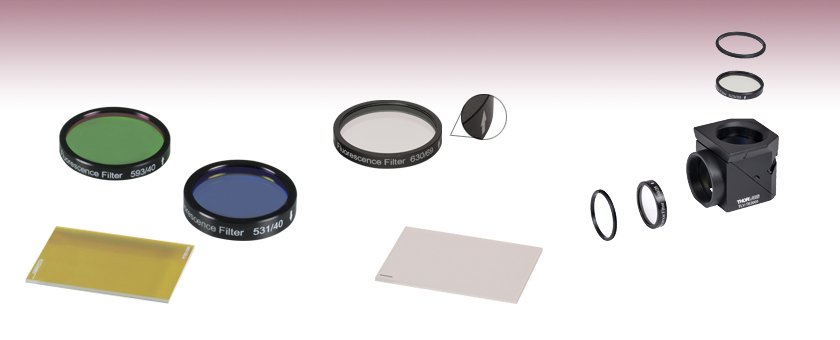
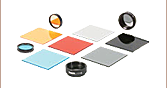
MD568
Dichroic Mirror
MDF-TOM
Filter Set
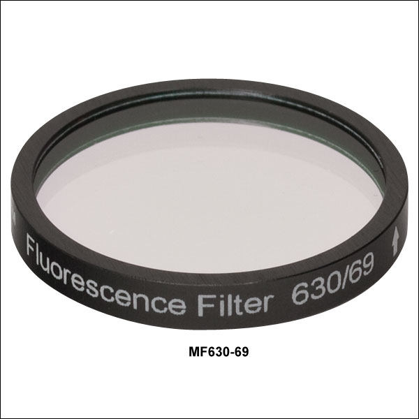
MF630-69
Emission Filter
Arrow Indicates
Direction of Light
Propagation
Etched Corner Indicates Dichroic-Coated Side
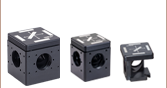
Exploded View of a Filter Set Installed Into a Filter Cube
Dichroic
Mirror
Inside Cube
Excitation
Filter
Emission
Filter
Image Plane
Retaining
Ring
Retaining
Ring


Please Wait
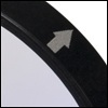
Excitation and emission filters are marked with an arrow that shows the recommended direction of light propagation.
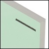
Dichroic filters have an engraving on or a caret pointing to the primary reflective surface. Light should be incident on this side for best performance.
Features
- Excitation, Emission, and Dichroic Filters for Fluorescence Imaging
- >90% Transmission over Desired Wavelength Band
- Sharp Cutoff (Up to T < 0.001%) Outside the Transmission Band
- Matched Filter Sets Designed to Target Many Common Fluorophores
- BFP
- CFP
- WGFP
- GFP
- FITC
-Alexa Fluor®∗ 488- YFP
- tdTomato
- TRITC
- Texas Red®*
- mCherry
- Cy®†3.5- Cy5
- Cy5.5
- Cy7
- LI-COR IRDye®‡ 800CW - Excitation and Emission Filters are Mounted in Black-Anodized Housings
- Dichroic Filters are Unmounted
- Filter Sets are Available at a Savings Over Individual Filter Prices
These excitation, emission, and dichroic filters are designed specifically for use in fluorescence imaging applications. They are fabricated at industry-standard dimensions that make them compatible with filter cubes from all major manufacturers. We offer filters designed to target the following common fluorophores: BFP, CFP, WGFP, GFP, FITC, Alexa Fluor 488, YFP, tdTomato, TRITC, Texas Red, mCherry, Cy3.5, Cy5, Cy5.5, Cy7, and LI-COR IRDye 800CW. While many of the filters are offered individually, some are only offered in a three-piece set containing the excitation, emission, and dichroic filters; see the Specs tab for details. A selection of these filters are also available pre-installed into our microscope filter cubes.
Filter Design
Our filters are manufactured to high-performance optical specifications and designed for durability. They are produced via multiple dielectric layers deposited on a high-precision, fused silica substrate. The substrate is ground and polished to ensure that the highest possible image quality is maintained. The resulting hard-coated optics consist of filter layers that are denser than those obtained from electron beam deposition techniques, and which reduce water absorption while greatly enhancing durability, stability, and performance of the filter. Each filter layer is monitored during growth to ensure minimal deviation from design specification thickness, ensuring overall high-quality filter performance.
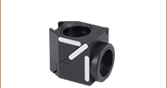
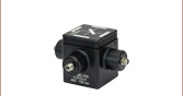
Each excitation or emission filter is housed in a Ø25 mm black anodized aluminum ring which makes handling easier and enhances the blocking OD by limiting scattering. These filters can be mounted in our extensive line of filter mounts and wheels. As the aluminum rings are not threaded, Ø1" retaining rings will be required to mount the Ø25 mm filters in one of our internally-threaded SM1 lens tubes. For customers who wish to use these filters in Thorlabs, Olympus, or Nikon fluorescence microscopes, Thorlabs manufactures a family of Drop-In Microscope Filter Cubes. Thorlabs also manufactures a family of 30 mm Cage Cubes to integrate these filters into a 30 mm cage system. Additionally, the unmounted dichroic filters can be mounted in the KM2536 kinematic mount, which is designed to secure a 1 mm thick rectangular optic with minimal stress.
∗Alexa Fluor and Texas Red are registered trademarks of Molecular Probes, Inc.
†Cy is a registered trademark of Global Life Sciences Solutions Germany GmbH
‡IRDye is a registered trademark of LI-COR Biotech, LLC
| Item # | Size | Clear Aperture | Angle of Incidence | Thickness | Surface Quality | Substrate |
|---|---|---|---|---|---|---|
| Excitation Filters | ||||||
| MDF-GFP2, MDF-TOM, MDF-MCHC, & MDF-MCHA Kits | Ø25 +0.0/-0.1 mm | >Ø21 mm | 0° ± 5 | 5.0 ± 0.1 mm | 60-40 Scratch-Dig |
Fused Silica |
| MDF-CY5, MDF-CY55, MDF-CY7, & MDF-NIR Kits | Ø25.0 ± 0.1 mm | ≥Ø22 mm | Alkaline Earth Boro-Aluminosilicate |
|||
| All Other Excitation Filters | Ø25 ± 0.1 mm | >Ø21 mm | Fused Silica | |||
| Emission Filters | ||||||
| MDF-GFP2, MDF-TOM, MDF-MCHC, & MDF-MCHA Kits | Ø25 +0.0/-0.1 mm | >Ø22 mm | 0° ± 5° | 3.5 ± 0.1 mm | 60-40 Scratch-Dig |
Fused Silica |
| MDF-CY5, MDF-CY55, MDF-CY7, & MDF-NIR Kits | Ø25.0 ± 0.1 mm | ≥Ø22 mm | ||||
| All Other Excitation Filters | Ø25 ± 0.1 mm | >Ø21 mm | ||||
| Dichroic Filters | ||||||
| MDF-GFP2, MDF-TOM, MDF-MCHC, & MDF-MCHA Kits | 25.2 mm x 35.6 mm | 80% of Area | 45° ± 1.5° | 1.05 ± 0.05 mm | 60-40 Scratch-Dig |
Fused Silica |
| MDF-CY5, MDF-CY55, MDF-CY7, & MDF-NIR Kits | 25.0 mm x 35.8 mm | ≥22 mm x 33 mm (Elliptical) | 1.0 ± 0.1 mm | |||
| All Other Excitation Filters | 25.0 mm x 36.0 mm | >(22.5 mm x 32.4 mm) | ||||
| Item # | Kit Item # |
Fluorophore | Filter Type |
Center Wavelength |
FWHM | Reflection Band |
Transmission Band |
AR Coatinga | Transmission Datab |
|---|---|---|---|---|---|---|---|---|---|
| MF390-18 | MDF-BFP | BFP | Excitation | 390 nm | 18 nm | - | - | - | |
| MF460-60 | Emission | 460 nm | 60 nm | - | - | - | |||
| MD416 | Dichroic | - | - | Ravg > 90% 360 - 407 nm |
Tabs > 90% 425 - 575 nm |
Rabs < 2% from 400 to 800 nm |
|||
| MF434-17 | MDF-CFP | CFP | Excitation | 434 nm | 17 nm | - | - | - | |
| MF479-40 | Emission | 479 nm | 40 nm | - | - | - | |||
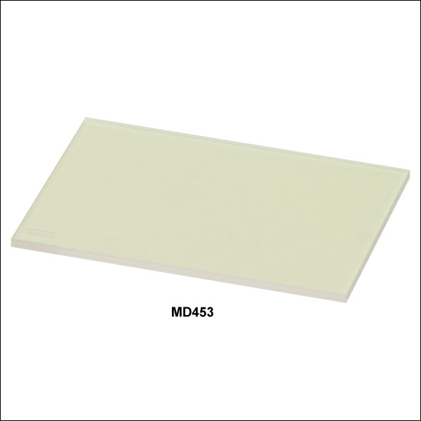
| MD453 | Dichroic | - | - | Ravg > 90% 423 - 445 nm |
Tabs > 90% 460 - 610 nm |
Rabs < 2% from 400 to 800 nm |
|||
| MF445-45 | MDF-WGFP | WGFP | Excitation | 445 nm | 45 nm | - | - | - | |
| MF510-42 | Emission | 510 nm | 42 nm | - | - | - | |||
| MD480 | Dichroic | - | - | Ravg > 90% 415 - 470 nm |
Tabs > 90% 490 - 720 nm |
Rabs < 2% from 400 - 800 nm |
|||
| MF469-35 | MDF-GFP | GFP | Excitation | 469 nm | 35 nm | - | - | - | |
| MF525-39 | Emission | 525 nm | 39 nm | - | - | - | |||
| MD498 | Dichroic | - | - | Ravg > 90% 452 - 490 nm |
Tabs > 90% 505 - 800 nm |
Rabs < 2% from 400 to 800 nm |
|||
| MF475-35 | MDF-FITC | FITC | Excitation | 475 nm | 35 nm | - | - | - | |
| MF530-43 | Emission | 530 nm | 43 nm | - | - | - | |||
| MD499 | Dichroic | - | - | Ravg > 90% 470 - 490 nm |
Tabs > 90% 508 - 675 nm |
Rabs < 2% from 400 to 800 nm |
|||
| - | MDF-GFP2 | GFP Alexa Fluor® 488 |
Excitation | 482 nm | 18 nm | - | - | - | |
| - | Emission | 520 nm | 28 nm | - | - | - | |||
| - | Dichroic | - | - | Ravg > 93% 350 - 488 nm |
Tavg > 93% 502 - 950 nm |
- | |||
| MF497-16 | MDF-YFP | YFP | Excitation | 497 nm | 16 nm | - | - | - | |
| MF535-22 | Emission | 535 nm | 22 nm | - | - | - | |||
| MD515 | Dichroic | - | - | Ravg > 90% 490 - 510 nm |
Tabs > 90% 525 - 700 nm |
- | |||
| - | MDF-TOM | tdTomato | Excitation | 531 nm | 40 nm | - | - | - | |
| - | Emission | 593 nm | 40 nm | - | - | - | |||
| - | Dichroic | - | - | Ravg > 98% 350 - 555 nm |
Tavg > 93% 569 - 950 nm |
- | |||
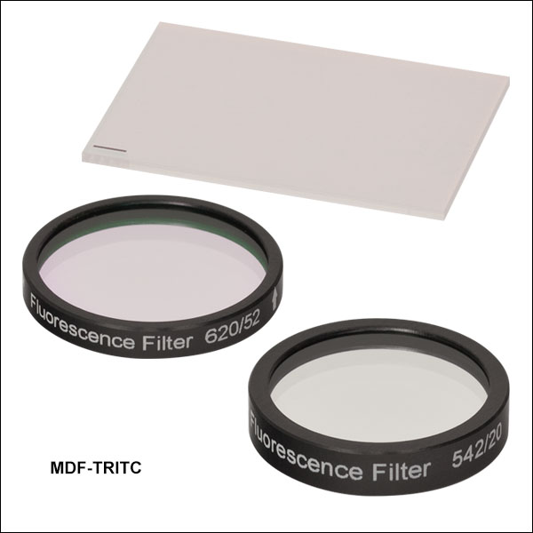
| MF542-20 | MDF-TRITC | TRITC | Excitation | 542 nm | 20 nm | - | - | - | |
| MF620-52c | Emission | 620 nm | 52 nm | - | - | - | |||
| MD568 | Dichroic | - | - | Ravg > 90% 525 - 556 nm |
Tabs > 90% 580 - 650 nm |
Rabs < 2% from 400 to 800 nm |
|||
| MF559-34 | MDF-TXRED | Texas Red® | Excitation | 559 nm | 34 nm | - | - | - | |
| MF630-69 | Emission | 630 nm | 69 nm | - | - | - | |||
| MD588d | Dichroic | - | - | Ravg > 90% 533 - 580 nm |
Tabs > 90% 595 - 800 nm |
Rabs < 2% from 400 to 800 nm |
|||
| - | MDF-MCHC | mCherry | Excitation | 562 nm | 40 nm | - | - | - | |
| - | Emission | 641 nm | 75 nm | - | - | - | |||
| - | Dichroic | - | - | Ravg > 98% 350 - 585 nm |
Tavg > 93% 601 - 950 nm |
- | |||
| MF565-24 | MDF-CY3.5 | Cy®3.5 | Excitation | 565 nm | 24 nm | - | - | - | |
| MF620-52c | Emission | 620 nm | 52 nm | - | - | - | |||
| MD588d | Dichroic | - | - | Ravg > 90% 533 - 580 nm |
Tabs > 90% 595 - 800 nm |
Rabs < 2% from 400 to 800 nm |
|||
| - | MDF-MCHA | mCherry | Excitation | 578 nm | 21 nm | - | - | - | |
| - | Emission | 641 nm | 75 nm | - | - | - | |||
| - | Dichroic | - | - | Ravg > 98% 350 - 588 nm |
Tavg > 93% 603 - 950 nm |
- | |||
| - | MDF-CY5 | Cy5 | Excitation | 619 nm | 60 nm | - | - | - | |
| - | Emission | 700 nm | 71 nm | - | - | - | |||
| - | Dichroic | - | - | Ravg ≥ 98% 500 - 648 nm |
Tavg ≥ 95% 666 - 890 nm |
- | |||
| - | MDF-CY55 | Cy5.5 | Excitation | 650 nm | 44 nm | - | - | - | |
| - | Emission | 720 nm | 59.5 nm | - | - | - | |||
| - | Dichroic | - | - | Ravg > 98% 520 - 674 nm |
Tavg ≥ 95% 692 - 1000 nm |
- | |||
| - | MDF-CY7 | Cy7 | Excitation | 709 nm | 75.5 nm | - | - | - | |
| - | Emission | 813 nm | 96 nm | - | - | - | |||
| - | Dichroic | - | - | Ravg > 98% 570 - 746 nm |
Tavg ≥ 95% 766 - 1100 nm |
- | |||
| - | MDF-NIR | LI-COR IRDye® 800CW | Excitation | 741 nm | 41 nm | - | - | - | |
| - | Emission | N/Ae | - | - | - | - | |||
| - | Dichroic | - | - | Ravg > 98% 580 - 760 nm |
Tavg ≥ 95% 780 - 1100 nm |
- |
- Select dichroics have an AR coating designed for 45° AOI on the back surface.
- Click on
 for a plot and downloadable data.
 - Designed to work with both TRITC and CY3.5.
- Designed to work with both CY3.5 and TXRED.
- This emission filter has a cut on wavelength of 780 nm with average transmission ≥94% for 790 - 1000 nm
 Click to Enlarge
Click to Enlarge
MDF-YFP filter set transmission graph. Note the dichroic mirror (green) reflects light in the excitation wavelength range (blue), and transmits light in the emission wavelength range (green).
Filters for Fluorescence Microscopy
Fluorophores
A fluorophore is a molecule or portion of a molecule that is capable of producing fluorescence. When light of the appropriate frequency necessary to excite a molecule from its ground state to an excited state is present, excitation will occur. However, once in an excited state, the molecule will be unstable. After some short period of time (typically 10-15 to 10-9 s), a photon will be released, thereby enabling the molecule to return to a lower energy state. The emitted radiation will be at a longer wavelength (lower energy) than the absorbed radiation due to the loss of energy through various mechanisms such as vibrations, sound, and thermal energy.
A single fluorophore can be continually excited unless it is destroyed by photobleaching (i.e. the nonreversible destruction of a fluorophore due to photon-induced chemical damage or covalent modification). The average number of excitation and emission cycles that a particular fluorophore can undergo prior to photobleaching depends on its molecular structure and the local environment; some fluorophores bleach quickly after emitting only a few photons while others are far more robust and can undergo thousands or even millions of cycles before bleaching occurs.
Filters for Fluorescence Microscopy
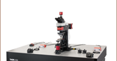
The experimental setup to the right shows the typical filters used for epi-fluorescence microscopy, a form of microscopy in which both the excitation and emission light travel through the microscope objective. By carefully choosing the appropriate filters and mirrors for a given application, the signal-to-noise ratio can be maximized. As shown in the schematic to the right, three types of filters are used to maximize the fluorescence signal while minimizing the unwanted radiation. Each optical element is discussed below.
Excitation Filter
The excitation filter only allows a narrow band of wavelengths to pass through it, around the peak fluorophore excitation wavelength. For example, as shown in the graph to the right, the bandpass region corresponding to greater than 90% transmission for the Yellow Fluorescent Protein (YFP) Excitation Filter (MF497-16) is 489 - 505 nm; incident radiation outside of this range is either partially (for regions near the transmission region) or totally (for regions further from the bandpass region) blocked by the filter.
Dichroic Mirror
Dichroic mirrors are designed to reflect light whose wavelength is below a specific value (i.e. the cutoff wavelength) while permitting all other wavelengths to pass through it unaltered. In a microscope, the dichroic mirror directs the proper wavelength range to the sample as well as to the image plane. The cutoff wavelength value associated with each mirror indicates the wavelength that corresponds to 50% transmission. For example, as shown in the graph to the right, the cutoff wavelength for the Yellow Fluorescent Protein (YFP) Dichroic Mirror (MD515) is ~515 nm. The Specs tab provides information on the reflectance and transmission for each type of dichroic mirror.
By placing one of these mirrors into the experimental setup at 45° with respect to the incident radiation, the excitation radiation (shown in blue in the above right schematic) is reflected off of the surface of the dichroic mirror and directed towards the sample and microscope objective, while the fluorescence emanating from the sample (shown in red in the above right schematic) passes through the mirror to the detection system.
Although dichroic mirrors play a crucial role in fluorescence microscopy, they are not perfect when it comes to blocking unwanted light; typically, ~90% of the light at wavelengths below the cutoff wavelength value are reflected and ~90% of the light at wavelengths above this value are transmitted by the dichroic mirror. Hence, some of the excitation light can be transmitted through the dichroic mirror along with the longer wavelength fluorescence emitted by the sample. To prevent this unwanted light from reaching the detection system, an emission filter is used in addition to the dichroic mirror.
Emission Filter
An emission filter serves the purpose of allowing the desirable fluorescence from the sample to reach the detector while blocking unwanted traces of excitation light. Like the excitation filter, this filter only allows a narrow band of wavelengths to pass through it, around the peak fluorophore emission wavelength. For example, as shown in the graph to the right, the bandpass region corresponding to greater than 90% transmission for the Yellow Fluorescent Protein (YFP) Emission Filter (MF535-22) is 524 - 546 nm; incident radiation outside of this range is either partially (for regions near the transmission region) or totally (for regions further from the bandpass region) blocked by the filter.
| Posted Comments: | |
Sashank Sriram
(posted 2025-03-30 21:06:51.65) Hi, I am curious if the dichroic mirrors presented here are polarisation sensitive. Since the mirrors are typically aligned at 45 degrees with the incoming beam of light, the electric fields can be either in-plane or out of the plane of the mirror. I would expect the two polarisations to interact differently with the components. Is there a significant difference in the performance of your dichroic mirrors versus the polarisation of light? blarowe
(posted 2025-03-31 03:37:27.0) Thank you for contacting Thorlabs. Generally, we would expect some polarization dependence from these filters. I've reached out to you directly with more details. Yuan Gong
(posted 2023-12-28 12:08:46.28) Hi,
May I ask about the absorption of the filters, like MF525-39? I would like to buy a pair of this product, and I care about its reflection in the stop band. Can I roughly calculate the reflection at a specific wavelength by R=1-T?
Many thanks! Have a nice one!
Yuan jpolaris
(posted 2024-01-16 04:30:35.0) Thank you for contacting Thorlabs. In general, R = 1-T is not a reliable estimate for reflectance in the stop band because it ignores the effects of absorption and interference which could be part of the blocking mechanism. I have reached out to directly with reflectance data. Priyanka Jangra
(posted 2023-09-13 22:19:46.323) We want to know about the product FMF003 availability and price jdelia
(posted 2023-09-13 01:33:48.0) Thank you for reaching out. FMF003 was obsoleted and replaced by MF535-22. You can find pricing and availability information for this product directly on the product family page. Kevin Cappa
(posted 2020-03-04 17:50:33.503) If I had the option to get a 2"/50mm filter set for FITC fluorescent imaging I would... nbayconich
(posted 2020-03-05 01:03:35.0) Thank you for your feedback, I will log your request in our internal engineering forum for future reference. We can provide custom sized filters upon request, I will reach out to you directly to discuss our custom capabilities. tcohen
(posted 2012-09-13 11:44:00.0) Response from Tim at Thorlabs: Thank you for your interest in our custom capabilities. We should be able to provide this as a special and I have contacted you to go over your requirements. densta
(posted 2012-09-13 12:33:11.0) Dear Madam/Sir
I want to perform some preliminary fluorescence tests for a project of ours.
I am interested in buying one of the following emission filters
MF525-39: GFP
MF530-43: FITC
I noticed from your records that the outer diameter of the filter is 25 mm.
In our system we need a filter with outer diameter 17 mm. The filter could be bare glass without an outer support ring. Is it possible to have one of the above mentioned filters in this form? What would be the cost?
Best regards,
Dimosthenis Stamopoulos bdada
(posted 2012-02-24 17:13:00.0) Response from Buki at Thorlabs to
Thank you for your interest in our imaging dichroic filters.
Testing has shown no signs of degradation when exposed to at least 6 W of power from an unfiltered xenon arc lamp over a 25 mm diameter (corresponding to 1.2 W/cm2) for over 500 hours.
Please contact TechSupport@thorlabs.com if you have any questions. user
(posted 2012-02-10 13:05:04.0) Can you please provide laser damage threshold ratings for the dichroic filters? jjurado
(posted 2011-03-22 16:05:00.0) Response from Javier at Thorlabs to flickingerd: Thank you for your feedback. Our filters follow that same convention as that of Semrock's. The arrow points to the recommended direction of light propagation. The reason for this is although the filter will function with either side facing the source, it is recommended to place the coated side toward the source. This will minimize any thermal effects or possible thermal damage that blocking intense out-of-band radiation might cause due to absorption by the substrate or colored glass filter layers. lmorgus
(posted 2011-03-21 18:23:00.0) A response from Laurie at Thorlabs to flickingerd: As a follow-up to the response you received earlier today from Javier in our technical support group, I wanted to also reach out to you to thank you for your feedback. We have updated our web presentation to provide information about what the arrow on these optic mounts indicates. As a further step, we have made a list of other web pages on our site that need some attention for similar reasons. In the coming days, we will be updating those pages to clarify our engravings so that our customers can efficiently find the information they need to use our products effectively. Again, thank you for taking the time to drop us a note with a suggestion for improvement. flickingerd
(posted 2011-03-21 14:29:07.0) I couldnt find info on proper filter orientation. There are arrows on the filters, but Ive seen different conventions on what these mean (Chroma says point arrow towards specimen for emission filters, yet Semrock convention is always point arrow in direction of light propagation, I think). How about your filters? This should be in "Tutorial" section, Id think. Please contact me with proper orientation rules. (Although Im still not sure exactly why this matters...I guess I can think of some minor reasons...) apalmentieri
(posted 2010-02-18 09:42:22.0) A response from Adam at Thorlabs to pludowise: I believe we should be able to offer this item as a custom option. I would like to contact you directly to get more information about your application, the quantity necessary, and the exact size of the optic. pludowise
(posted 2010-02-18 00:01:38.0) I am interested in finding a dichroic filter similar to MDF-TXRED, but shifted to loger wavelengths. Specifically, I need a dichroic for a Cy5 dye, which needs to transmit at 640 nm, and reflect at 690 nm. I also need this in a 1 mm thickness mounted at 45 deg AOI. Thank you. |

 Zoom
Zoom| Item # | Transmission Dataa |
Design Fluorophore | Center Wavelength | FWHM |
|---|---|---|---|---|
| MF390-18 | Blue Fluorescent Protein (BFP) | 390 nm | 18 nm | |
| MF434-17 | Cyan Fluorescent Protein (CFP) | 434 nm | 17 nm | |
| MF445-45 | Wild Type GFP (WGFP) | 445 nm | 45 nm | |
| MF469-35 | Green Fluorescent Protein (GFP) | 469 nm | 35 nm | |
| MF475-35 | Fluorescein isothiocyanate (FITC) | 475 nm | 35 nm | |
| MF497-16 | Yellow Fluorescent Protein (YFP) | 497 nm | 16 nm | |
| MF542-20 | Tetramethylrhodamine Isothiocyanate (TRITC) | 542 nm | 20 nm | |
| MF559-34 | Texas Red® (TXRED) | 559 nm | 34 nm | |
| MF565-24 | Cy®3.5 (CY3.5) | 565 nm | 24 nm |
- Click on
 for a plot and downloadable data.
These excitation fluorescence imaging filters are specifically designed to be used in microscopy and imaging applications. Each Ø25 mm filter is mounted in a 5 mm thick black anodized housing. The housing has an arrow engraved on it that points in the recommended light propagation direction.
These filters provide excellent transmission of the desired excitation wavelength (>90%), with a sharp spectral cutoff and low transmission at other wavelengths (<0.001%). Click on the ![]() icons above to view product-specific transmission data.
icons above to view product-specific transmission data.

 Zoom
Zoom| Item # | Transmission Dataa |
Design Fluorophore | Center Wavelength | FWHM |
|---|---|---|---|---|
| MF460-60 | Blue Fluorescent Protein (BFP) | 460 nm | 60 nm | |
| MF479-40 | Cyan Fluorescent Protein (CFP) | 479 nm | 40 nm | |
| MF510-42 | Wild Type GFP (WGFP) | 510 nm | 42 nm | |
| MF525-39 | Green Fluorescent Protein (GFP) | 525 nm | 39 nm | |
| MF530-43 | Fluorescein isothiocyanate (FITC) | 530 nm | 43 nm | |
| MF535-22 | Yellow Fluorescent Protein (YFP) | 535 nm | 22 nm | |
| MF620-52 | Tetramethylrhodamine Isothiocyanate/ Cy®3.5 (TRITC/CY3.5) |
620 nm | 52 nm | |
| MF630-69 | Texas Red® (TXRED) | 630 nm | 69 nm |
- Click on
 for a plot and downloadable data.
These emission fluorescence imaging filters are specifically designed to be used in microscopy and imaging applications. Each Ø25 mm filter is mounted in a 3.5 mm thick black anodized housing. The housing has an arrow engraved on it that points in the recommended light propagation direction.
These filters provide excellent transmission of the desired emission wavelength (>90%), with a sharp spectral cutoff and low transmission at other wavelengths (<0.001%). Click on the ![]() icons above to view product-specific transmission data.
icons above to view product-specific transmission data.

 Zoom
Zoom| Item # | Transmission Dataa |
Design Fluorophore | Reflection Bandb |
Transmission Bandc |
|---|---|---|---|---|
| MD416 | Blue Fluorescent Protein (BFP) | 360 - 407 nm | 425 - 575 nm | |
| MD453 | Cyan Fluorescent Protein (CFP) | 423 - 445 nm | 460 - 610 nm | |
| MD480 | Wild Type GFP (WGFP) | 415 - 470 nm | 490 - 720 nm | |
| MD498 | Green Fluorescent Protein (GFP) | 452 - 490 nm | 505 - 800 nm | |
| MD499 | Fluorescein isothiocyanate (FITC) | 470 - 490 nm | 508 - 675 nm | |
| MD515 | Yellow Fluorescent Protein (YFP) | 490 - 510 nm | 525 - 700 nm | |
| MD568 | Tetramethylrhodamine Isothiocyanate (TRITC) | 525 - 556 nm | 580 - 650 nm | |
| MD588 | Cy®3.5/Texas Red® (CY3.5/TXRED) | 533 - 580 nm | 595 - 800 nm |
- Click on
 for a plot and downloadable data.
 - Average reflection is >90% within this range.
- Absolute transmission is >90% within this range.
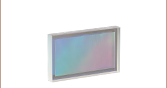
Thorlabs' Dichroic Filters are designed to separate light of different wavelengths. When light is incident on the filter at a 45° angle with respect to the normal, the excitation light and its associated back reflection are reflected while the longer wavelength fluorescence signal is transmitted. These filters are unmounted, but are marked by a dash to indicate the coated side of the filter, which light should be incident on. Each filter is 25.0 mm x 36.0 mm. If your application would benefit from a round, mounted dichroic filter, consider our round Dichroic Filters. Click on the ![]() icons above to view product-specific transmission data.
icons above to view product-specific transmission data.

 Zoom
Zoom| Item # | Transmission Dataa |
Design Fluorophore | Excitation Band |
Emission Band |
Dichroic (Reflection / Transmission Band) |
|---|---|---|---|---|---|
| MDF-BFP | Blue Fluorescent Protein (BFP) | 390 ± 9 nm | 460 ± 30 nm | 360 - 407 nm / 425 - 475 nm | |
| MDF-CFP | Cyan Fluorescent Protein (CFP) | 434 ± 8.5 nm | 479 ± 20 nm | 423 - 445 nm / 460 - 610 nm | |
| MDF-WGFP | Wild Type GFP (WGFP) | 445 ± 22.5 nm | 510 ± 21 nm | 415 - 470 nm / 490 - 720 nm | |
| MDF-GFP | Green Fluorescent Protein (GFP) | 469 ± 17.5 nm | 525 ± 19.5 nm | 452 - 490 nm / 505 - 800 nm | |
| MDF-FITC | Fluorescein Isothiocyanate (FITC) | 475 ± 17.5 nm | 530 ± 21.5 nm | 470 - 490 nm / 508 - 675 nm | |
| MDF-GFP2 | Green Fluorescent Protein (GFP)/ Alexa Fluor® 488 |
482 ± 9 nm | 520 ± 14 nm | 350 - 488 nm / 502 - 950 nm | |
| MDF-YFP | Yellow Fluorescent Protein (YFP) | 497 ± 8 nm | 535 ± 11 nm | 490 - 510 nm / 525 - 700 nm | |
| MDF-TOM | tdTomato | 531 ± 20 nm | 593 ± 20 nm | 350 - 555 nm / 569 - 950 nm | |
| MDF-TRITC | Tetramethylrhodamine Isothiocyanate (TRITC) |
542 ± 10 nm | 620 ± 26 nm | 525 - 556 nm / 580 - 650 nm | |
| MDF-TXRED | Texas Red® (TXRED) | 559 ± 17 nm | 630 ± 34.5 nm | 533 - 580 nm / 595 - 800 nm | |
| MDF-MCHC | mCherry | 562 ± 20 nm | 641 ± 37.5 nm | 350 - 585 nm / 601 - 950 nm | |
| MDF-CY3.5 | Cy®3.5 | 565 ± 12 nm | 620 ± 26 nm | 533 - 580 nm / 595 - 800 nm | |
| MDF-MCHA | mCherry | 578 ± 10.5 nm | 641 ± 37.5 nm | 350 - 588 nm / 603 - 950 nm | |
| MDF-CY5 | Cy5 | 619 ± 30 nm | 700 ± 35.5 nm | 500 - 648 nm / 666 - 890 nm | |
| MDF-CY55 | Cy5.5 | 650 ± 22 nm | 720 ± 30 nm | 520 - 674 nm / 692 - 1000 nm | |
| MDF-CY7 | Cy7 | 709 ± 38 nm | 813 ± 48 nm | 570 - 746 nm / 766 - 1100 nm | |
| MDF-NIR | LI-COR IRDye® 800CW | 741 ± 20.5 nm | 780 nm (Cut-On) | 580 - 760 nm / 780 - 1100 nm |
- Click on
 for a plot and downloadable data.
Since standard fluorescence imaging applications generally incorporate three different filters (i.e., one excitation, one emission, and one dichroic filter) to maximize the signal-to-noise ratio, Thorlabs offers these filters as a set at a savings over purchasing each compenent separately. Some excitation, emission, and dichroic filters are only available as a matched set and are not available for purchase individually.
Please note some excitation and emission filter housings have an arrow engraved on them that points in the recommended direction of light propagation. Dichroic filters have an engraving on or a caret pointing to the side with the primary reflective coating. Light should be incident on this designated side of the optic for optimal performance.